")
XLF Series
- Output Voltages to 60kV
- Integrated Floating Filament Supply; "Hot Cathode"
- Negative Polarity
- Local & Remote Programming
*Note: All specifications are subject to change without notice. Please consult the English PDF version of this datasheet for the most up-to-date revision.


600-1200W Industrial X-Ray Generators
Spellman’s XLF Series of X-Ray generators are well regulated high voltage power supplies with output voltages to 60kV and very low ripple achieved through the use of advanced resonant conversion techniques. Extremely stable voltage and emission current outputs result in significant performance improvements over previously available technology. The XLF Series provides power, control and support functions required for X-Ray applications including a regulated ac filament supply referenced to the cathode. These units also incorporate local and remote programming, monitoring, safety interlock, short-circuit and overload protection.
Typical applications:
- Plastics Sorting
- Crystal Inspection
- Diamond Inspection
Specifications
(Ref. 128011-001 REV. N)
Input Voltage:
XLF 600W:
115Vac ±10% @ 11.4A, 50-60Hz single phase
220Vac ±10% @ 5.9A, 50-60Hz single phase
XLF 1200W:
220Vac ±10% @ 11.8A, 50-60Hz single phase
Voltage and Current Control:
Local: continuously adjustable from zero to maximum rating via a ten-turn potentiometer
Remote: 0 to +10Vdc proportional from 0 to full output
Accuracy: ±1%
Input Impedance: 10Mohm
Filament:
12 volts @ 5 amps, preheat level is 0.45 amps in standby
Voltage Regulation:
Load: 0.005% of full output voltage no load to full load
Line: 0.005% for input voltage range change
Current Regulation:
Load: 0.05% of full current ±100µA from 0 to full voltage
Line: 0.05% of rated current over specified input range
Ripple:
0.03% rms below 1kHz
0.75% rms above 1kHz
Temperature Coefficient:
100ppm/°C.
Stability:
0.01%/8 hrs after 1/2 hour warm-up
0.02% per 8 hours (typical)
Cooling:
Fan cooled
Metering:
Digital voltage and current meters (3.5 digits), 1% accuracy
Voltage and Current Monitors:
0 to +10Vdc proportional to rated output
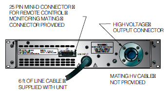
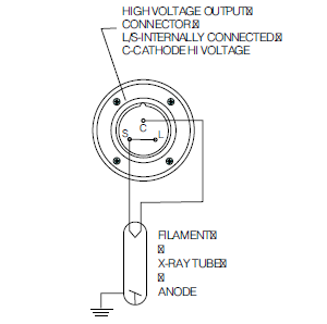
HV Output:
75kV, 3 conductor Federal Standard X-Ray connector
I/O Connectors:
25 pin D-type for control interface with mating connector provided
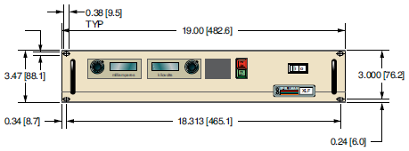
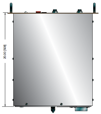
Dimensions:
3.5”H x 19”W x 20”D (8.9cm x 48.3cm x 50.8cm)
Regulatory Approvals:
Compliant to EEC EMC Directive. Compliant to EEC Low Voltage Directive. RoHS compliant
FRONT PANEL STATUS INDICATORS:
Overvoltage Voltage Control Mode
Overtemperature Current Control Mode
Regulation Error Interlock Open
Arc Interlock Closed
HV ON: Red HV OFF: Green
OPTIONS
APT - Adjustable Power Trip
AT - Arc Trip
SS(x) - Non-Standard Slow Start
NSS - No Slow Start
IO - Instant ON
SL - Slides
Electronic Component (Power Source)
XLF series is intended for installation as a component of a system. It is designed to meet CE standards, with conditions of acceptance often being: customer provided enclosure mounting, EMC filtering, and appropriate protection, and isolation devices. The XLF series is not intended to be operated by end users as a stand-alone device. The XLF series power supply can only be fully assessed when installed within a system, and as a component part within that system.
600W, 1200W XLF SELECTION TABLE
| 600 Watt | 1200 Watt | ||||
|---|---|---|---|---|---|
| kV | mA | Model | kV | mA | Model |
| 30 | 20 | XLF30N600 | 30 | 40 | XLF30N1200 |
| 40 | 15 | XLF40N600 | 40 | 30 | XLF40N1200 |
| 50 | 12 | XLF50N600 | 50 | 24 | XLF50N1200 |
| 60 | 10 | XLF60N600 | 60 | 20 | XLF60N1200 |
JB1 CONNECTOR 25 PIN
| Pin | Signal | Signal Parameters |
|---|---|---|
| 1 | Power Supply Common | Signal Ground |
| 2 | External Inhibit | Ground=Inhibit, Open=HV On |
| 3 | External Interlock | +15V at Open, <15mA at Closed |
| 4 | External Interlock Return | Return for Interlock |
| 5 | Current Monitor | 0 to 10V=0 to 100% Rated Output |
| 6 | kV Test Point | 0 to 10V=0 to 100% Rated Output |
| 7 | +10V Reference | +10Vdc @ 1mA Max |
| 8 | Remote Current Program In | 0 to 10V=0 to 100% Rated Output |
| 9 | Local Current Program Out | Front Panel Program Voltage |
| 10 | Remote Voltage Program In | 0 to 10V=0 to 100% Rated Output |
| 11 | Local Voltage Program Out | Front Panel Program Voltage |
| 12 | Power Monitor | 0 to 10V=0 to 100% Rated Output (Optional) |
| 13 | Remote Power Program In | 0 to 10V=0 to 100% Rated Output (Optional) |
| 14 | Local HV Off Out | +15V at Open, <25mA at Closed Connect to HV OFF for Fp Operation |
| 15 | HV Off | +15V at Open, <25mA at Closed Connect to HV OFF for Fp Operation |
| 16 | Remote HV On | +15V, 10mA Max=HV Off 0=HV On, +15V, 10mA Max=HV Off |
| 17 | Remote HV Off Indicator | +15V, 10mA Max=HV Off 0=HV On, +15V, 10mA Max=HV Off |
| 18 | Remote HV On Indicator | 0=HV Off, +15V, 10mA Max=HV On |
| 19 | Remote Voltage Mode | Open Collector 50V Max, 10mA Max On=Active |
| 20 | Remote Current Mode | Open Collector 50V Max, 10mA Max On=Active |
| 21 | Remote Power Mode | Open Collector 50V Max, 10mA Max On=Active |
| 22 | Remote PS Fault | 0=Fault, +15V, 0.1mA Max=No Fault |
| 23 | +15V Output | +15V, 100mA Max |
| 24 | Power Supply Common | Signal Ground |
| 25 | Shield Return | Shield Return |
Tables & Diagrams
DIMENSIONS: in.[mm]
FRONT VIEW
TOP VIEW
BACK VIEW
HIGH VOLTAGE CONNECTOR PINOUT
Frequently Asked Questions
Application Notes AN-12 – The Benefit of Using a Current Source to Power X-Ray Tube Filament Circuits
Application Notes AN-14 – The Limits of Front Panel Digital Meters
Application Notes AN-15 – 3.5 And 4.5 Digit Meter Displays Explained
Application Notes AN-23 – SL HV Off and HV on Circuitry Explained
Application Notes AN-01 – Fundamentals of X-Ray Generator – X-Ray Tube Optimization

