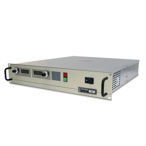
XLFシリーズ
- 最大出力電圧60kV
- 内蔵浮遊フィラメント電源「ホットカソード」
- 負極性
- ローカル、リモートプログラミング
*注: すべての仕様は予告なく変更される場合があります。最新版についてはこのデータシートの英語PDFをご覧ください。


600~1200W産業用X線ジェネレーター
XLFシリーズは、X線発生用高圧直流電源で出力電圧範囲は 60kVまでです。また、高精度な共振コンバータ技術により、リッ プルは大変低くなっています。出力電圧および管電流の安定度に より、既存の技術での性能を大幅に改善しました。このシリーズ は、カソードにリファレンスしたACフィラメントを含む、X線 用途に必要な電力制御、サポート機能を提供しています。また、 ローカル及びリモートのプログラム、モニタリング、安全インター ロックや短絡、過負荷の保護回路なども内蔵されています。
用途
- プラスチック選別
- 鉱石検査
- ダイヤモンド検査
![]()
Specifications
(Ref. 128011-001 REV. N)
Input Voltage:
XLF 600W:
115Vac ±10% @ 11.4A, 50-60Hz single phase
220Vac ±10% @ 5.9A, 50-60Hz single phase
XLF 1200W:
220Vac ±10% @ 11.8A, 50-60Hz single phase
Voltage and Current Control:
Local: continuously adjustable from zero to maximum rating via a ten-turn potentiometer
Remote: 0 to +10Vdc proportional from 0 to full output
Accuracy: ±1%
Input Impedance: 10Mohm
Filament:
12 volts @ 5 amps, preheat level is 0.45 amps in standby
Voltage Regulation:
Load: 0.005% of full output voltage no load to full load
Line: 0.005% for input voltage range change
Current Regulation:
Load: 0.05% of full current ±100µA from 0 to full voltage
Line: 0.05% of rated current over specified input range
Ripple:
0.03% rms below 1kHz
0.75% rms above 1kHz
Temperature Coefficient:
100ppm/°C.
Stability:
0.01%/8 hrs after 1/2 hour warm-up
0.02% per 8 hours (typical)
Cooling:
Fan cooled
Metering:
Digital voltage and current meters (3.5 digits), 1% accuracy
Voltage and Current Monitors:
0 to +10Vdc proportional to rated output
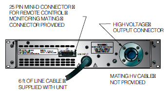
HV Output:
75kV, 3 conductor Federal Standard X-Ray connector
I/O Connectors:
25 pin D-type for control interface with mating connector provided
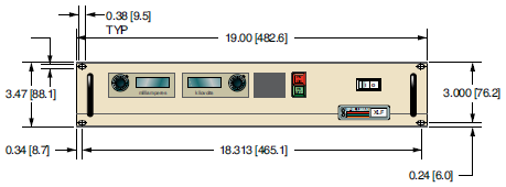
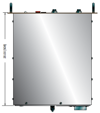
Dimensions:
3.5”H x 19”W x 20”D (8.9cm x 48.3cm x 50.8cm)
Regulatory Approvals:
Compliant to EEC EMC Directive. Compliant to EEC Low Voltage Directive. RoHS compliant
FRONT PANEL STATUS INDICATORS:
Overvoltage Voltage Control Mode
Overtemperature Current Control Mode
Regulation Error Interlock Open
Arc Interlock Closed
HV ON: Red HV OFF: Green
OPTIONS
APT - Adjustable Power Trip
AT - Arc Trip
SS(x) - Non-Standard Slow Start
NSS - No Slow Start
IO - Instant ON
SL - Slides
Electronic Component (Power Source)
XLF series is intended for installation as a component of a system. It is designed to meet CE standards, with conditions of acceptance often being: customer provided enclosure mounting, EMC filtering, and appropriate protection, and isolation devices. The XLF series is not intended to be operated by end users as a stand-alone device. The XLF series power supply can only be fully assessed when installed within a system, and as a component part within that system.
600W, 1200W XLF SELECTION TABLE
| 600 Watt | 1200 Watt | ||||
|---|---|---|---|---|---|
| kV | mA | Model | kV | mA | Model |
| 30 | 20 | XLF30N600 | 30 | 40 | XLF30N1200 |
| 40 | 15 | XLF40N600 | 40 | 30 | XLF40N1200 |
| 50 | 12 | XLF50N600 | 50 | 24 | XLF50N1200 |
| 60 | 10 | XLF60N600 | 60 | 20 | XLF60N1200 |
JB1 CONNECTOR 25 PIN
| Pin | Signal | Signal Parameters |
|---|---|---|
| 1 | Power Supply Common | Signal Ground |
| 2 | External Inhibit | Ground=Inhibit, Open=HV On |
| 3 | External Interlock | +15V at Open, <15mA at Closed |
| 4 | External Interlock Return | Return for Interlock |
| 5 | Current Monitor | 0 to 10V=0 to 100% Rated Output |
| 6 | kV Test Point | 0 to 10V=0 to 100% Rated Output |
| 7 | +10V Reference | +10Vdc @ 1mA Max |
| 8 | Remote Current Program In | 0 to 10V=0 to 100% Rated Output |
| 9 | Local Current Program Out | Front Panel Program Voltage |
| 10 | Remote Voltage Program In | 0 to 10V=0 to 100% Rated Output |
| 11 | Local Voltage Program Out | Front Panel Program Voltage |
| 12 | Power Monitor | 0 to 10V=0 to 100% Rated Output (Optional) |
| 13 | Remote Power Program In | 0 to 10V=0 to 100% Rated Output (Optional) |
| 14 | Local HV Off Out | +15V at Open, <25mA at Closed Connect to HV OFF for Fp Operation |
| 15 | HV Off | +15V at Open, <25mA at Closed Connect to HV OFF for Fp Operation |
| 16 | Remote HV On | +15V, 10mA Max=HV Off 0=HV On, +15V, 10mA Max=HV Off |
| 17 | Remote HV Off Indicator | +15V, 10mA Max=HV Off 0=HV On, +15V, 10mA Max=HV Off |
| 18 | Remote HV On Indicator | 0=HV Off, +15V, 10mA Max=HV On |
| 19 | Remote Voltage Mode | Open Collector 50V Max, 10mA Max On=Active |
| 20 | Remote Current Mode | Open Collector 50V Max, 10mA Max On=Active |
| 21 | Remote Power Mode | Open Collector 50V Max, 10mA Max On=Active |
| 22 | Remote PS Fault | 0=Fault, +15V, 0.1mA Max=No Fault |
| 23 | +15V Output | +15V, 100mA Max |
| 24 | Power Supply Common | Signal Ground |
| 25 | Shield Return | Shield Return |
Tables & Diagrams
DIMENSIONS: in.[mm]
FRONT VIEW
TOP VIEW
BACK VIEW
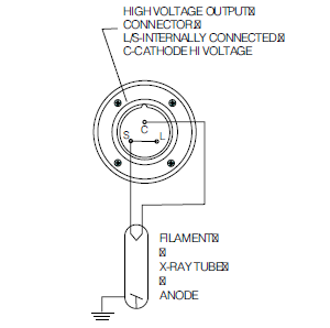
HIGH VOLTAGE CONNECTOR PINOUT
Frequently Asked Questions
Application Notes AN-12 – The Benefit of Using a Current Source to Power X-Ray Tube Filament Circuits
Application Notes AN-14 – The Limits of Front Panel Digital Meters
Application Notes AN-15 – 3.5 And 4.5 Digit Meter Displays Explained
Application Notes AN-23 – SL HV Off and HV on Circuitry Explained
Application Notes AN-01 – Fundamentals of X-Ray Generator – X-Ray Tube Optimization

