")
XRV Series
- 160kV, 225kV, 320kV, 350kV and 450kV Models
- Complete X-Ray Generator Package
- Power Factor Corrected AC Input Circuitry
- Integrated Dual Filament Supplies
- Digital Interface—USB, Ethernet and RS-232
- Excellent Stability and Regulation
- Available with Black Powder Coated Finish

![]()

*Note: All specifications are subject to change without notice. Please consult the English PDF version of this datasheet for the most up-to-date revision.
1.8 - 6kW Industrial X-Ray Generators
Spellman’s XRV series of X-Ray high voltage power supplies sets the standard for compact 1.8kW to 6.0kW, high performance X-Ray inspection generators. Spanning an output voltage range of 160kV to 450kV in negative, positive or bipolar output configurations, there’s a model available for virtually every application requirement.
Active power factor correction circuitry reduces input current requirements while minimizing line related EMI. Spellman’s proprietary inverter topology allows for unprecedented efficiencies and power densities. A solid encapsulated high voltage section further reduces size and weight and provides reliable, maintenance free operation.
DSP based SMT control circuitry provides your choice of USB, Ethernet and RS-232 along with analog interfacing, simplifying OEM system integration. The two DC output, current regulated filament power supplies are controlled via sophisticated emission current regulation circuitry to provide accurate and stable X-Ray tube currents. Comprehensive fault diagnostic circuitry, and Arc Sense, Arc Quench and Arc Count functionality is also incorporated into this compact, space saving X-Ray generator.
Specifications
(Ref. 128060-001 REV. AE)
Typical Applications
Non Destructive TestingX-Ray Scanning
Security Applications
Medical Applications
Options
400Vac ±10% (6kW only)
GUI Control Software for XRV
XRVC (XRV Controller)
Specifications
Input Voltage:
1.8kW, 3.0kW, 4.0kW and 4.5kW models:
180-264Vac, single phase, 47-63 Hertz, active power factor corrected input to ≥0.98
6.0kW models:
208 or 400Vac, ±10%, three phase, 47-63 Hertz, passive power factor corrected
Input Current:
1.8kW, 3.0kW, 4.0kW and 4.5kW models: <30 amps
6.0kW models: <25 amps per phase
Output Voltage:
Accuracy: 0.25%
Stability: ≤ 0.1% per 8 hours, after 1 hour warm up
1.8kW, 3.0kW, 4.0kW and 4.5kW models:
Load:±0.05% of rated output voltage for a full load change
Line: ±0.05% of rated output voltage over specified input voltage range
6.0kW models:
Load:±0.1% of rated output voltage for a full load change
Line: ±0.1% of rated output voltage over specified input voltage range
Output Polarity:
See “model selection” table
Output Current:
See “model selection” table
Ripple:
See “model selection” table
Temperature Coefficient:
1.8kW, 3.0kW, 4.0kW and 4.5kW models:
50ppm/°C
6.0kW models:
±50ppm/°C
Emission Current:
Accuracy: 0.25%
Stability: 100ppm/°C
1.8kW, 3.0kW, 4.0kW and 4.5kW models:
Load: ±0.05% of rated output current for a change from 30% to 100% of rated output voltage
Line: ±0.05% of rated output current over specified input voltage range
6.0kW models:
Load: ±0.1% of rated output current for a change from 30% to 100% of rated output voltage
Line: ±0.1% of rated output current over specified input voltage range
Filament:
Output:
0-6 amps at a compliance of 10Vdc, maximum
Dual Focal Spot:
Small and large, selectable via interface signal
Configuration:
DC filament drive. Closed loop emission control regulates filament setting to provide desired X-Ray tube emission current
Control Interface:
Remote Interface:
Analog, USB, Ethernet and RS-232 are standard
Control Software:
A Windows graphical user interface example is provided.
Environmental
Temperature Range:
Operating: 0°C to +50°C
Storage: -40°C to +85°C
Humidity:
20% to 85% RH, non-condensing
Mains Input Connector:
1.8kW, 3.0kW, 4.0kW and 4.5kW models:
Type 97-3102A-24-11P
6.0kW models:
Type 97-3102A-24-22P
Interface Connectors:
Digital—Ethernet, RS-232 and USB
Analog—25 pin connector
Output Connector:
See “model selection” table
Cooling:
Forced air
Regulatory Approvals:
Compliant to EEC EMC Directive/Compliant to EEC Low Voltage Directive. File E227588. RoHS Compliant.
XRV160/320/350 SPECIFICATIONS
| XRV160*1800 | XRV160*3000 | XRV160*4000 | XRV160*6000 | XRV320P&N1800 | XRV320P&N4500 | XRV350P&N4500 | |
|---|---|---|---|---|---|---|---|
| DC Output Voltage | 5kV to 160kV | 5kV to 160kV | 5kV to 160kV | 5kV to 160kV | 5kV to ±160kV | 5kV to ±160kV | 5kV to ±175kV |
| Polarity* | Pos or Neg | Pos or Neg | Pos or Neg | Pos or Neg | Bipolar | Bipolar | Bipolar |
| Output Rated Current | 0-30mA | 0-30mA | 0-50mA | 0-50mA | 0-30mA | 0-30mA | 0-30mA |
| Output Power | 1.8kW | 3.0kW | 4.0kW | 6.0kW | 1.8kW | 4.5kW | 4.5kW |
| Ripple/Noise (p-p) | <0.025% | <0.05% | <0.1% | <0.25% | <0.025% | <0.1% | <0.1% |
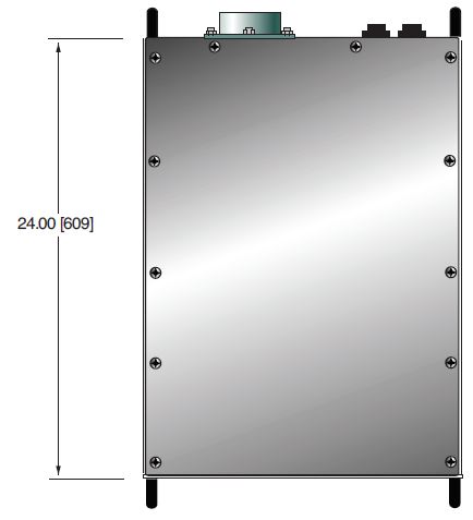
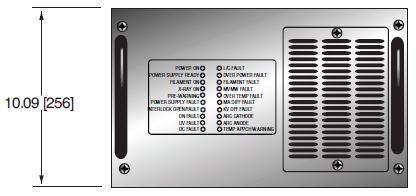
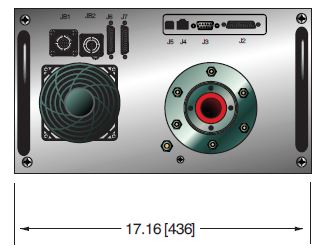
| Dimensions | 10.09˝ H x 17.16˝ W x 24˝ D (256mm x 436mm x 609mm) | 2 x (10.09˝ H x 17.16˝ W x 24˝ D) (256mm x 436mm x 609mm) | |||||
| Weight | 150 lbs. (68kg) | 150 lbs. (68kg) | 150 lbs. (68kg) | 155 lbs. (70.3kg) | 300 lbs. (136 kg) | 300 lbs. (136 kg) | 300 lbs. (136 kg) |
| Output Connector | R24 | R24 | R24 | R24 | Two R24 | Two R24 | Two R24 |
XRV225/450 SPECIFICATIONS
| XRV225*1800 | XRV225*3000 | XRV225*4000 | XRV225*6000 | XRV450P&N1800 | XRV450P&N4500 | |
|---|---|---|---|---|---|---|
| DC Output Voltage | 5kV to 225kV | 5kV to 225kV | 5kV to 225kV | 5kV to 225kV | 5kV to ±225kV | 5kV to ±225kV |
| Polarity* | Pos or Neg | Pos or Neg | Pos or Neg | Pos or Neg | Bipolar | Bipolar |
| Output Rated Current | 0-30mA | 0-30mA | 0-30mA | 0-30mA | 0-30mA | 0-30mA |
| Output Power | 1.8kW | 3.0kW | 4.0kW | 6.0kW | 1.8kW | 4.5kW |
| Ripple/Noise (p-p) | <0.025% | <0.05% | <0.1% | <0.25% | <0.025% | <0.1% |
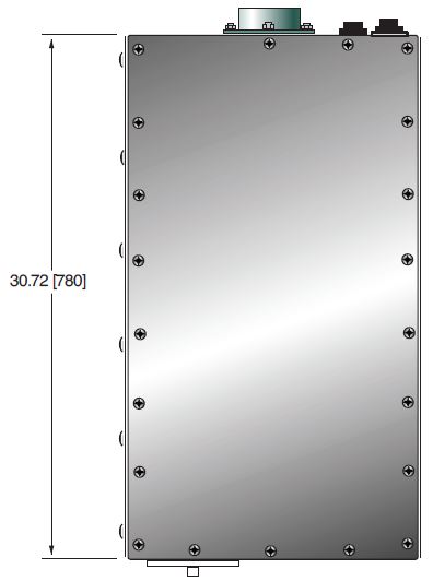
| Dimensions | 15.90˝ H x 17˝ W x 30.72˝ D (404mm x 432mm x 780mm) | 2 x (15.90˝ H x 17˝ W x 30.72˝ D) (404mm x 432mm x 780mm) | ||||
| Weight | 240 lbs. (109kg) | 240 lbs. (109kg) | 240 lbs. (109kg) | 480 lbs. (218 kg) | 480 lbs. (218 kg) | |
| Output Connector | R28** | R28** | R28** | Two R28** | Two R28** | |
Units are available in positive output polarity without filament, see model selection table for ordering details.
*Specify “P” for positive or “N” for negative polarity.
**Order SHV HV cable flange p/n 407141-024 if using Comet HV cable with R28SL spring loaded plug.
| Pin | Signal | Parameters |
|---|---|---|
| C | HV Output | XRV160 and XRV320—R24 Connector XRV225 and XRV450—R28 Connector |
| S | Small Filament Output | 0 to 6 amps @ 10Vdc |
| L | Large Filament Output | 0 to 6 amps @ 10Vdc |
J2 ANALOG INTERFACE—25 PIN D CONNECTOR
| Pin | Signal | Parameters |
|---|---|---|
| 1 | Power Supply Fault | Low, sum of faults, HVPS detected a fault, open collector, 50V @ 10mA max |
| 2 | mA Program | 0 to 10V FS Z in = 10M ohms |
| 3 | kV Program | 0 to 10V FS Z in = 10M ohms |
| 4 | Filament Limit L/S Ref.* | 0 to 10V FS Z in = 10M ohms |
| 5 | Filament Preheat L/S Ref.* | 0 to 10V FS Z in = 10M ohms |
| 6 | kV Monitor | 0 to 10V FS Z out = 4.99k ohms |
| 7 | mA Monitor | 0 to 10V FS Z out = 4.99k ohms |
| 8 | Filament Current Monitor* | 0 to 10V FS Z out = 4.99k ohms |
| 9 | Signal Ground | Ground |
| 10 | X-Ray Enable | +24Vdc = X-Ray ON, connect to pin 14 with dry contact relay |
| 11 | Filament ON* | Filament ON status, low, filament is ON open collector 50V, @ 10mA max |
| 12 | Interlock 1 | Active low, interlock is closed, safe to enable HV |
| 13 | Interlock 2 | Active low, interlock is closed, safe to enable HV |
| 14 | +24Vdc | +24Vdc @ 100mA, maximum |
| 15 | Filament Enable* | Active low, turn filament ON |
| 16 | Filament Control* | Active low, filament is regulated by ECR (HV must be ON). Not active, the filament is regulated by the preheat reference |
| 17 | Filament L/S Select | Filament selection large or small, low = small spot is selected |
| 18 | Filament L/S Confirm | Open collector, 50V @ 10mA max Filament selection confirm, low = small spot is selected |
| 19 | HVPS RDY | Low = HVPS ready, open collector, 50V @ 10mA max |
| 20 | X-Ray ON | X-Ray ON status, low = X-Rays are ON open collector, 50V @ 10mA max |
| 21 | Interlock Status | Low, interlocks are closed, can enable HV open collector, 50V @ 10mA max |
| 22 | GND | Digital ground |
| 23 | X-Ray ON Pre-Warn | Pre-warning, low, before X-Ray ON open collector, 50V @ 10mA max |
| 24 | Reset | Active low, minimum 10mS transition |
| 25 | Arc fault | Low, arc fault, the HVPS has detected an arc open collector, 50V @ 10mA max |
*Not active on positive models
MODEL SELECTION TABLE
| Model | Voltage | Power | Polarity |
|---|---|---|---|
| XRV160*1800 | 160kV | 1.8kW | Pos or Neg |
| XRV160*3000 | 160kV | 3.0kW | Pos or Neg |
| XRV160*4000 | 160kV | 4.0kW | Pos or Neg |
| XRV160*6000/208V | 160kV | 6.0kW | Pos or Neg |
| XRV160*6000/400V | 160kV | 6.0kW | Pos or Neg |
| XRV225*1800 | 225kV | 1.8kW | Pos or Neg |
| XRV225*3000 | 225kV | 3.0kW | Pos or Neg |
| XRV225*4000 | 225kV | 4.0kW | Pos or Neg |
| XRV225*6000/208V | 225kV | 6.0kW | Pos or Neg |
| XRV225*6000/400V | 225kV | 6.0kW | Pos or Neg |
| XRV320P&N1800 | ±160kV | 1.8kW | Bipolar |
| XRV320P&N4500 | ±160kV | 4.5kW | Bipolar |
| XRV350P&N4500 | ±175kV | 4.5kW | Bipolar |
| XRV450P&N1800 | ±225kV | 1.8kW | Bipolar |
| XRV450P&N4500 | ±225kV | 4.5kW | Bipolar |
*Specify “P” for positive or “N” for negative polarity. Positive polarity models do not have
integrated filament power supplies. Contact Spellman for custom output voltage/power models.
RS-232 DIGITAL INTERFACE—J3 9 PIN FEMALE D CONNECTOR
| Pin | Signal | Parameters |
|---|---|---|
| 1 | N/C | No Connection |
| 2 | TX out | Receive Data |
| 3 | RX in | Transmit Data |
| 4 | N/C | No Connection |
| 5 | SGND | Ground |
| 6 | N/C | No Connection |
| 7 | N/C | No Connection |
| 8 | N/C | No Connection |
| 9 | N/C | No Connection |
ETHERNET DIGITAL INTERFACE—J4 8 PIN RJ45 CONNECTOR
| Pin | Signal | Parameters |
|---|---|---|
| 1 | VBUS | +5 Vdc |
| 2 | D- | Data - |
| 3 | D+ | Data + |
| 4 | GND | Ground |
JB1 MAIN AND AUXILIARY INPUT POWER—TYPE 97-3102A-24-11P (Single Phase Units)
| Pin | Signal | Parameters |
|---|---|---|
| A | Auxiliary AC Line Power | 180-264Vac |
| B | Auxiliary Ground | Ground |
| C | Auxiliary AC Neutral | Neutral |
| D | Main AC Line Power | 180-264Vac |
| E | Main Ground | Ground |
| F | Main AC Neutral | Neutral |
JB1 MAIN AC INPUT POWER—TYPE 97-3102A-24-22P (Three Phase Units)
| Pin | Signal | Parameters |
|---|---|---|
| A | Line 1 | 208Vac, ±10%, 50/60Hz @ 25 amps |
| B | Line 2 | 208Vac, ±10%, 50/60Hz @ 25 amps |
| C | Line 3 | 208Vac, ±10%, 50/60Hz @ 25 amps |
| D | GND | Ground |
Note: Use 4 conductor cable or single isolated wires rated no
less that 600Vac, 30 amps (10AWG, minimum)
JB2 AUXILIARY AC INPUT POWER—TYPE 97-3102A-20-3P (Three Phase Units)
| Pin | Signal | Parameters |
|---|---|---|
| A | Line 1 | 208Vac, ±10%, 50/60Hz (source 3 phase L1, L2) |
| B | Line 2 | 208Vac, ±10%, 50/60Hz (source 3 phase L1, L2) |
| C | GND | Ground |
System Ground: System ground wires (10AWG minimum) to
the ground terminal E1 GND to the power supply using ground
stud M6 X 20MM, with M6 nut.
Tables & Diagrams
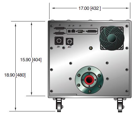
DIMENSIONS: in.[mm]
XRV160
TOP VIEW
FRONT VIEW
REAR VIEW
XRV225
TOP VIEW
FRONT VIEW
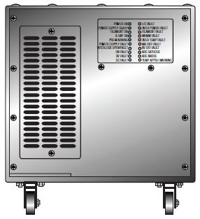
REAR VIEW
Frequently Asked Questions
Application Notes AN-12 – The Benefit of Using a Current Source to Power X-Ray Tube Filament Circuits
Application Notes AN-01 – Fundamentals of X-Ray Generator – X-Ray Tube Optimization

