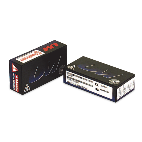
UM Series
- 8 Voltage Ranges from 62.5V to 6kV, Fixed Negative or Positive Polarity
- Available Output Power Increments of 4, 20 and 30 Watts
- Voltage/Current Regulation with Automatic Crossover Control
- Voltage and Current Monitor Signals
- Fully Arc and Short Circuit Protected
- Precision +5V Reference Output
- Comprehensive Standard Interface
- CE Listed, UL Recognized and RoHS Compliant
Certifications & Compliance



DC-DC High Voltage Power Supplies
Form, Fit and Function Design:
Spellman’s UM Series of printed circuit board mountable, high voltage modules offer a form, fit and function replacement for presently available commercially made units, while providing additional features and benefits at competitive pricing. Utilizing proprietary power conversion technology and Spellman's six decades of high voltage experience, these SMT based high voltage modules provide improved performance/reliability and easier system integration at a lower cost when compared to the competition.
Advanced Power Conversion Topology:
UM converters use a proprietary zero voltage switching power conversion topology providing exceptional efficiency and inherent low noise and ripple. Radiated emissions are reduced compared to conventional switching topologies, minimizing or even eliminating the need to shield the unit from adjacent circuitry.
The high voltage output is generated using a ferrite core high voltage step up transformer which feeds the output circuitry. Units at 1kV or higher utilize an arrangement of half wave Cockcroft-Walton voltage multiplier stages to obtain the specified high voltage output, while lower voltage units use a robust rectification and filter circuit.
Due to the fixed, high frequency conversion rate the output capacitance is small resulting in minimal stored energy. Through the use of generously rated surge limiting resistors and a fast acting current loop, all units are fully arc and short circuit protected.
Control and Regulation:
The actual output voltage generated is sampled via a high impedance divider to create a voltage feedback signal. A current feedback signal is created via a current sense resistor in the low end return of the high voltage output circuitry. These two accurate ground referenced feedback signals are used to precisely regulate and control the units in addition to external monitoring purposes.
Due to the UM’s unique converter topology it can provide full current into low impedance loads or even a short circuit. Standard units limit at 103% of maximum rated output current.
Standard Interface:
The Spellman UM Series interface provides current programming capability and positive polarity, buffered, low output impedance voltage and current monitor signals (zero to +4.64Vdc equals zero to full scale rated). A voltage programming input is provided where 0 to +4.64Vdc equals 0 to 100% of rated voltage. Current programmability allows the user to set where the unit will current limit, anywhere from 0 to 100% of maximum rated current. This feature is beneficial where less than full output current is desired, like in the case of protecting a sensitive load.
The buffered low impedance voltage and current monitor signals can drive external circuitry directly, while minimizing loading and pickup effects. These features save the user the expense and implementation of external interface buffering circuitry while improving overall signal integrity. This standard interface is made available via a row of 13 pins with 0.1. pin spacing. A legacy interface (7 pins on a 0.2. spacing) that is compatible with presently available commercially made units can be provided by ordering the “L” option.
Mechanical and Environmental Considerations:
The UM Series are solid encapsulated, printed circuit board mountable, plastic cased converters measuring only 2.97. X 1.5. X 0.83. (75.4mm X 38.1mm X 21.1mm). All units are encapsulated using a silicon based potting material which is considerably lighter in weight than epoxy. Two isolated, non grounded 2-56 machine screws thread into the module to securely mount it to the printed circuit board, relieving any stress on the interface pins. Mounting plates, brackets and flanged mounting options are also available.
- Specifications
- Models
- How to Order
- Downloads
Specifications
- Input Voltage:
12Vdc for 4W, 24Vdc for 20W and 30W - Nominal Voltage Range:
11Vdc to 30Vdc for 4W, 23Vdc to 30Vdc for 20W and 30W - Input Current:
(typical) - Disabled:
30mA - No load:
90mA - Full load:
4 watt units:
0.5A
20 watt units:
1.0A
30 watt units:
1.5A - Dimensions:
2.97" L X 1.49" W X 0.81" H (75.2mm X 37.9mm X 20.6mm)
Models
UM 4W SELECTION TABLE
| Model Number | Output V | Output Current | Low Freq. Ripple %Vp-p @ 1Hz-1kHz | High Freq. Ripple %Vp-p @ 1kHz-1MHz | Output Capacitance | Arc Limiting Resistanc | I Sense Scaling Full Scale Signal | High Voltage Divider Resistance |
|---|---|---|---|---|---|---|---|---|
| UM0.062*4 | 0 to 62.5V | 64mA | 0.030 | 0.028 | 8.8μF | 1Ω | 1.5V | 0.5MΩ |
| UM0.125*4 | 0 to 125V | 32mA | 0.045 | 0.014 | 8.8μF | 4.4Ω | 2.75V | 0.88MΩ |
| UM0.25*4 | 0 to 250V | 16mA | 0.034 | 0.017 | 2.2μF | 20Ω | 4.9V | 1.50MΩ |
| UM0.5*4 | 0 to 500V | 8mA | 0.036 | 0.040 | 0.8μF | 94Ω | 10.1V | 2.65MΩ |
| UM1*4 | 0 to 1KV | 4mA | 0.025 | 0.015 | 0.2μF | 470Ω | 10.75V | 20MΩ |
| UM2*4 | 0 to 2kV | 2mA | 0.022 | 0.015 | 0.097μF | 1.0KΩ | 10.4V | 30MΩ |
| UM4*4 | 0 to 4kV | 1mA | 0.019 | 0.017 | 0.012μF | 9.4KΩ | 11.1V | 100MΩ |
| UM6*4 | 0 to 6kV | 0.67mA | 0.016 | 0.015 | 0.007μF | 20KΩ | 9.9V | 150MΩ |
UM 20W SELECTION TABLE
| Model Number | Output V | Output Current | Low Freq. Ripple %Vp-p @ 1Hz-1kHz | High Freq. Ripple %Vp-p @ 1kHz-1MHz | Output Capacitance | Arc Limiting Resistance | I Sense Scaling Full Scale Signal | High Voltage Divider Resistance |
|---|---|---|---|---|---|---|---|---|
| UM0.062*20 | 0 to 62.5V | 320mA | 1Hz-1kHz 0.060 | 0.088 | 8.8μF | 1Ω | 330mV | 0.5MΩ |
| UM0.125*20 | 0 to 125V | 160mA | 0.067 | 0.044 | 8.8μF | 4.4Ω | 675mV | 0.88MΩ |
| UM0.25*20 | 0 to 250V | 80mA | 0.035 | 0.019 | 2.2μF | 20Ω | 1.135V | 1.50MΩ |
| UM0.5*20 | 0 to 500V | 40mA | 0.041 | 0.040 | 0.8μF | 94Ω | 2.25V | 2.65MΩ |
| UM1*20 | 0 to 1KV | 20mA | 0.039 | 0.095 | 0.2μF | 470Ω | 4.35V | 20MΩ |
| UM2*20 | 0 to 2kV | 10mA | 0.026 | 0.016 | 0.097μF | 1.0KΩ | 6.6V | 30MΩ |
| UM4*20 | 0 to 4kV | 5mA | 0.023 | 0.028 | 0.012μF | 9.4KΩ | 6.65V | 100MΩ |
| UM6*20 | 0 to 6kV | 3.3mA | 0.017 | 0.018 | 0.007μF | 20KΩ | 6.74V | 150MΩ |
UM 30W SELECTION TABLE
| Model Number | Output V | Output Current | Low Freq. Ripple %Vp-p @ 1Hz-1kHz | High Freq. Ripple %Vp-p @ 1kHz-1MHz | Output Capacitance | Arc Limiting Resistance | I Sense Scaling Full Scale Signal | High Voltage Divider Resistance |
|---|---|---|---|---|---|---|---|---|
| UM0.062*30 | 0 to 62.5V | 480mA | 0.075 | 0.112 | 8.8μF | 1Ω | 500mV | 0.5MΩ |
| UM0.125*30 | 0 to 125V | 240mA | 0.075 | 0.056 | 8.8μF | 4.4Ω | 930mV | 0.88MΩ |
| UM0.25*30 | 0 to 250V | 120mA | 0.055 | 0.031 | 2.2μF | 20Ω | 1.65V | 1.50MΩ |
| UM0.5*30 | 0 to 500V | 60mA | 0.085 | 0.041 | 0.8μF | 94Ω | 3.4V | 2.65MΩ |
| UM1*30 | 0 to 1KV | 30mA | 0.032 | 0.171 | 0.2μF | 220Ω | 6.5V | 20MΩ |
| UM2*30 | 0 to 2kV | 15mA | 0.031 | 0.112 | 0.097μF | 470Ω | 9.85V | 30MΩ |
| UM4*30 | 0 to 4kV | 7.5mA | 0.028 | 0.071 | 0.012μF | 4.4KΩ | 9.85V | 100MΩ |
| UM6*30 | 0 to 6kV | 5mA | 0.020 | 0.051 | 0.007μF | 9.4KΩ | 10.0V | 150MΩ |
Note: Total ripple is the sum of the low frequency and high frequency ripple. Grayed text indicates Legacy interface signals.
How to Order
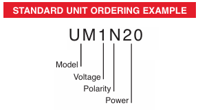
ORDERING INFORMATION
| Voltage | 0 to 62.5Vdc | 0.062 |
| | 0 to 125Vdc | 0.125 |
| | 0 to 250Vdc | 0.25 |
| | 0 to 500Vdc | 0.5 |
| | 0 to 1000Vdc | 1 |
| | 0 to 2000Vdc | 2 |
| | 0 to 4000Vdc | 4 |
| | 0 to 6000Vdc | 6 |
| Polarity | Positive | P |
| | Negative | N |
| Power | Watts Output | 4 |
| | Watts Output | 20 |
| | Watts Output | 30 |
STANDARD UNIT ORDERING EXAMPLE
Downloads

Service Solution Brochure
Spellman Repair Centers, Extended Warranty Programs, Preventative Maintenance Programs, Calibration Services and more.
Download
2026 High Voltage Reference Manual
We compiled all of our useful FAQ’s, application notes, articles, technical papers and three glossaries into a single handy reference guide.
DownloadSubscribe to our high voltage newsletter
Subscribe to our high voltage newsletter, published quarterly with relevant information on high voltage power supply technology and applications.