")
EVA Series
- Designed for E Beam Coating Applications
- 3kW, 6kW and 12kW Power Levels
- Remote Analog and Ethernet/RS-232 Interface
- Fast, User Configurable Dynamic Arc Intervention
- Optional Filament Gun Supply (up to 3 channels)
*Note: All specifications are subject to change without notice. Please consult the English PDF version of this datasheet for the most up-to-date revision.

![]()
E-beam Evaporation High Voltage Power Supply
Spellman’s new EVA Series is specifically designed for demanding electron beam coating applications. A full featured front panel provides local control, while an extensive analog interface allows remote capability. The included Ethernet and RS-232 digital interfaces simplify integrating the EVA into your system design.
The EVA’s robust IGBT inverter design is inherently fault tolerant. The proprietary low capacitance, low stored energy high voltage output section is ideal for dynamic load and fault conditions encountered in coating applications. Fast arc recovery times (<2ms) minimize process interruptions. Many operational parameters can be configured by the user to suit their particular requirements
An optional filament gun supply is available. The EVA can support one, two or three filament gun supply channels providing unprecedented flexibility and cost effectiveness.
Specifications
(Ref. 128106-001 REV. F)
3/6/12KW HV SPECIFICATIONS
Input Voltage: (must be specified at time of order)
Option 3PH: 180-264Vac, 50/60Hz, three phase, 90% efficiency, 0.85 power factor
Option 1PH: 180-264Vac 50/60Hz, single phase, 90% efficiency, 0.65 power factor (3kW & 6kW only)
Option 400VAC: 360-528Vac 50/60Hz, three phase, 90% efficiency, 0.85 power factor (6kW & 12kW only)
Input Current:
Option 3PH: 180-264Vac, 50/60Hz, three phase
3kW—13 amps, maximum
6kW—25 amps, maximum
12kW—50 amps, maximum
Option 1PH: 180-264Vac, 50/60Hz, single phase
3kW—29 amps, maximum
6kW—57 amps, maximum
Option 400VAC: 360-528Vac, 50/60 Hz, three phase,
6kW—13 amps, maximum
12kW—25 amps, maximum
Output Voltage:
5kV @ 600mA, negative polarity. 3kW maximum.
10kV @ 600mA, negative polarity. 6kW maximum.
10kV @ 1200mA, negative polarity. 12kW maximum.
Local Output Controls:
Voltage is continuously adjustable over entire range via a 10 turn potentiometer.
Voltage Regulation:
Load: 0.05% of full voltage +500mV for full load change.
Line: 0.05%of full voltage +500mV over specified input range.
Ripple:
<3% Vrms
Stability:
0.02%hr. after 1 hour warm-up.
Temperature Coefficient:
100ppm/°C.
Environmental:
Temperature Range:
Operating: 0°C to 40°C
Storage: -40°C to 85°C
Humidity:
10% to 90% RH, non-condensing.
Cooling:
Forced air; inlet through side panels, outlet at rear panel
Metering:
Front panel digital voltage and current meters, 3.5 digit, accurate to within 1%.
3/6/12KW HV SPECIFICATIONS
System Status Display:
“Dead Front” type indicators provide status of up to 12 system parameters including voltage regulation, fault conditions and circuit control.
Input Power Connector:
A 6 foot (1.8 meter) long captive line cord will be provided.
Analog Interface Connector:
50 pin female D connector
High Voltage Output Cable:
10 ft (3.05m) shielded high voltage cable, removable at rear panel.
Dimensions:
3kW/6kW Units: 5.25”(3U)H x 19” W x 21” D (133mm x 482mm x 533mm)
12kW Units: 10.5”(6U)H x 19” W x 21” D (266mm x 482mm x 533mm)
Weight:
3kW/6kW Units: 46 pounds (20.87kg)
12kW Units: 90 pounds (40.82kg)
Regulatory Approvals:
Compliant to EEC EMC Directive. Compliant to EEC Low Voltage Directive. UL/CUL recognized file E227588. RoHS compliant.
Digital Interface
The EVA features a standard RS-232 and Ethernet digital interface, simplifying power supply communication requirements saving the user time and money, while enhancing functionality and overall capability. Spellman provides a GUI allowing customization of operational features while also providing basic power supply functionality and control via a sample simulated front panel.
Arc Intervention
Spellman’s EVA power supplies sense arc events via a fast acting current sense transformer. The arc intervention circuitry prevents power supply damage from continuous, long term arcing. Customers can change arc intervention parameters (Arc Count, Arc Quench, Reramp Time, and Window Time) within preset limits via the provided GUI. Customized units can be configured for unique arc prone environments, contact Spellman for details.
Additional High Voltage Output Connectors
Spellman’s EVA is designed to provide 1, 2 or 3 parallel configured high voltage output connectors. The standard unit provides one high voltage output connector. If you intend to use the EVA in a multi channel application but want to utilize your own filament power supply, this factory installed option provides the additional high voltage connections required. Hardware Option HV2 provides two high voltage output connectors, while Hardware Option HV3 pro-vides three high voltage output connectors.
Multiple beam control units can be provided, allowing 1, 2 or 3 separate electron guns to be independently operated.
Each beam control unit consists of a beam controller and a gun output box. The beam controller is a 1U rack-mounted chassis containing the filament power, control and emission regulation circuitry. The gun output box contains the high frequency filament transformer which is referenced to the high voltage output potential. This box should be mounted close to the electron gun to minimize the length of the high current filament connections. The box also contains electron gun emission current monitoring circuitry and provides a feedback signal used to regulate the electron gun emission current.
Each beam control channel, if operated alone, can utilize 0 to 100% of the rated emission current capacity. When two or three beam control channels are used at the same time, the total system emission current capacity remains the same. Individual channel programming must be done such that the total current does not exceed the system’s total emission current available.
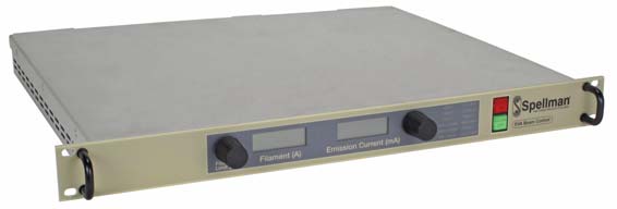
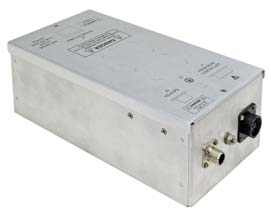
Optional Beam Controller (Filament Power Supply) and Gun Output Box
Beam Controller 1.75. (1U) Chassis
Gun Output Box
BEAM CONTROLLER SPECIFICATIONS
Input Voltage:
180-264 Vac, 50/60Hz, single phase, 7.5 amps maximum
Output Voltage/Current:
0-12Vrms at ˜ 30kHz, 0-35 amps. An optional 50 amp filament (HPF) is available.
Metering:
Front panel digital filament current and emission current meters, 3.5 digit, accurate to within 1%.
System Status Display:
“Dead Front” type indicators provide status of up to 12 system operations including voltage regulation, fault conditions and circuit control.
Input Power Connector:
A 6 foot (1.8 m) long IEC320 Cord Set will be provided.
Analog Interface Connector:
Male 25 pin D connector
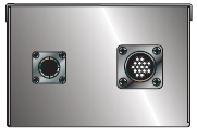
Filament Output Connections: (gun drive cable)
The secondary leads of the filament power transformer exiting the gun output box are 36” (91.44cm) long. The cover of this box is interlocked for safety purposes.
Environmental:
Temperature Range:
Operating: 0°C to 40°C
Storage: -40°C to 85°C
Humidity:
10% to 90% RH, non-condensing.
Cooling:
Forced air; inlet through side panels, outlet at rear panel.
Dimensions:
Beam Controller:
1.75”H (1U) x 15” W x 19”D (4.45 x 48.3 X 38.1cm)
Gun Output Box:
4”H x 6.25”W x 10”D (10.2 x 15.9 x 25.4cm)
Weight:
Beam Controller:
18 pounds (8.1kg)
Gun Output Box:
6 pounds (2.7kg)
HARDWARE BASED OPTIONS
3PH - 180-264Vac Three Phase Input
1PH - 180-264Vac Single Phase Input (3kW & 6kW only)
400VAC - 360-528Vac, Three Phase Input (6kW & 12kW only)
LL(X) - High Voltage Cable Length
HV2 - Two High Voltage Output Connectors
HV3 - Three High Voltage Output Connectors
FIL1 - Filament Gun Supply—One Channel
FIL2 - Filament Gun Supply—Two Channels
FIL3 - Filament Gun Supply—Three Channels
HPF - 50 Amp Filament Supply
SOFTWARE CONFIGURABLE FEATURES
Adjustable Overload Trip
Arc Trip Count
Arc Quench Time
Arc Reramp Time
Arc Window Time
HV POWER SUPPLY INTERFACE— 50 PIN FEMALE D CONNECTOR
| Pin | Signal | Parameters |
|---|---|---|
| 1 | Power Supply Common | Power Supply Ground |
| 2 | Reset/HV Inhibit | Normally open, Low = Reset/Inhibit |
| 3 | External Interlock | +24Vdc @ open, <25mA @ closed |
| 4 | External Interlock Return | Return for External Interlock |
| 5 | mA Test Point | 0-10Vdc = 0-100% rated output, Zout= 1KΩ, 1% |
| 6 | kV Test Point | 0-10Vdc = 0-100% rated output, Zout= 1KΩ, 1% |
| 7 | +10Vdc Reference Output | +10Vdc @ 1mA |
| 8 | mA Program Input | 0-10Vdc = 0-100% rated output, Zin>10MΩ |
| 9 | Local mA Program Output | 0-10Vdc = 0-100% rated output, front panel pot |
| 10 | kV Program Input | 0-10Vdc = 0-100% rated output, Zin>10MΩ |
| 11 | Local kV Program Output | 0-10Vdc = 0-100% rated output, front panel pot |
| 12 | Remote Power On Output | +24Vdc @ open, <25mA @ closed |
| 13 | Remote Power On Return | Return for Remote Power On |
| 14 | Remote HV Off | +24Vdc @ open, <25mA @ closed, connect to pin15 for front panel operation |
| 15 | Remote HV Off/On Common | HV On/Off Common |
| 16 | Remote HV On | +24Vdc @ open, <25mA @ closed, momentarily connect to pin 15 enable high voltage |
| 17 | HV Off Indicator | +24Vdc @ 25mA = HV Off |
| 18 | HV On Indicator | +24Vdc @ 25mA = HV On |
| 19 | Power Supply Common | Supply Ground |
| 20 | +24Vdc Output | +24Vdc @ 100mA, maximum |
| 21 | Voltage Mode Status | Open Collector, Low = Active |
| 22 | Current Mode Status | Open Collector, Low = Active |
| 23 | Spare | |
| 24 | Interlock Closed Status | Open Collector, Low = Active |
| 25 | Spare | |
| 26 | Spare | |
| 27 | Spare | |
| 28 | Remote Overvoltage Ad | 0-10Vdc = 0-100% rated output |
| 29 | Spare | |
| 30 | Over Voltage Fault | Open Collector, Low = Active |
| 31 | Over Current Fault | Open Collector, Low = Active |
| 32 | System Fault | Open Collector, Low = Active |
| 33 | RGLT Error Fault | Open Collector, Low = Active |
| 34 | Arc | Open Collector, Low = Active |
| 35 | Over Temp Fault | Open Collector, Low = Active |
| 36 | AC Fault | Open Collector, Low = Active |
| 37 | Spare | |
| 38 | Spare | |
| 39 | Spare | |
| 40 | Spare | |
| 41 | Spare | |
| 42 | Spare |
|
| 43 | Spare | |
| 44 | +5Vdc Output | +5Vdc @ 100mA, maximum |
| 45 | +15Vdc Output | +15Vdc @ 100mA, maximum |
| 46 | -15Vdc Output | -15Vdc @ 10mA, maximum |
| 47 | RS232 Tx | |
| 48 | RS232 Rx | |
| 49 | RS232 GND | |
| 50 | Power Supply Common | Power Supply Ground |
BEAM CONTROLLER INTERFACE— 25 PIN FEMALE D CONNECTOR
| Pin | Signal | Signal Parameters |
|---|---|---|
| 1 | Power Supply Common | Signal Ground |
| 2 | Spare | |
| 3 | External Interlock | +15Vdc at Open, <15mA @ Closed |
| 4 | External Interlock Return | Return for Interlock |
| 5 | Filament Current Test Point | 0 to 10Vdc = 0 to 100% rated output |
| 6 | Beam Current Test Point | 0 to 10Vdc = 0 to 100% rated output |
| 7 | +10Vdc Reference | +10Vdc, 1mA Max |
| 8 | Filament Limit Program Input | 0 to 10Vdc = 0 to 100% rated output |
| 9 | Local Filament Limit Program | Front panel potentiometer wiper |
| 10 | Beam Current Program Input | 0 to 10Vdc = 0 to 100% rated output |
| 11 | Local Beam Current Program | Front panel potentiometer wiper |
| 12 | Filament Preheat Program In | 0 to 10Vdc = 0 to 100% rated output |
| 13 | Local Fil. Preheat Program | Internal potentiometer |
| 14 | Beam Off | +15Vdc at Open, <25mA @ Closed Connect together for FP operation |
| 15 | Beam On/Off Common | +15Vdc at Open, <25mA @ Closed Connect together for FP operation |
| 16 | Beam On | Momentarily connect to pin 15 = Beam On |
| 17 | Remote Beam Off Indicator | 0=Beam On, +15V, 10mA Max=Beam Off |
| 18 | Remote Beam On Indicator | 0=Beam Off, +15V, 10mA Max=Beam On |
| 19 | Spare | |
| 20 | Spare | |
| 21 | Spare | |
| 22 | Remote PS Fault | 0 = Fault, +15Vdc @ 0.1mA = No Fault |
| 23 | Spare | |
| 24 | Power Supply Common | Signal Ground |
| 25 | Shield Return | Chassis Ground |
Tables & Diagrams
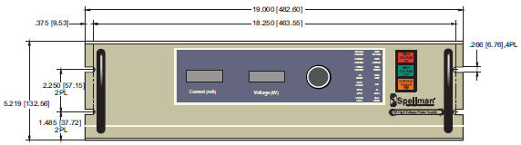
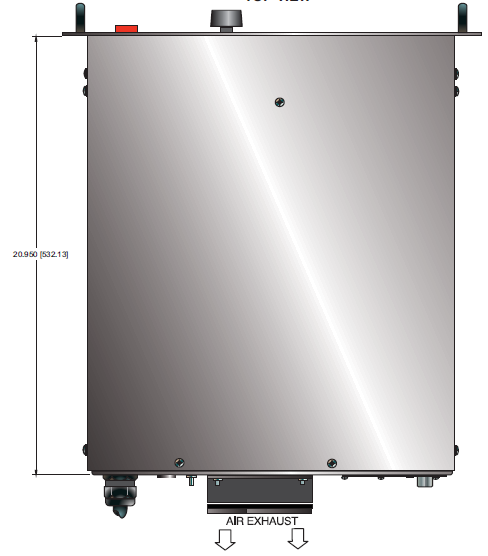
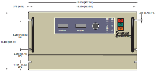
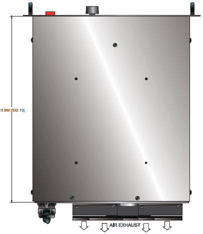
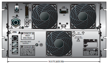
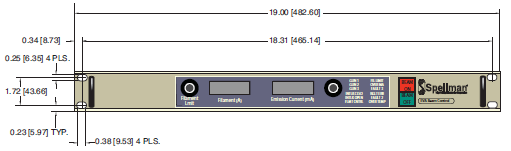
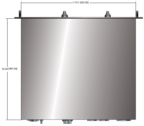
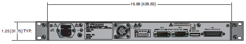
DIMENSIONS: in.[mm]
3U 6kW Power Supply
FRONT VIEW
TOP VIEW
BACK VIEW
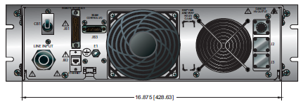
DIMENSIONS: in.[mm]
6U 12kW Power Supply
FRONT VIEW
TOP VIEW
BACK VIEW
DIMENSIONS: in.[mm]
Beam Controller
FRONT VIEW
TOP VIEW
BACK VIEW
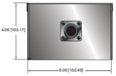
DIMENSIONS: in.[mm]
Gun Output Box
FRONT VIEW
TOP VIEW
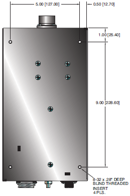
BACK VIEW
Frequently Asked Questions
What Is a Safe Level of High Voltage?
Where Can I Obtain Information on High Voltage Safety Practices?
How Should I Ground Your Supply?

