Series PFE - SB
- 6kVから20kVまで対応可能
- 30kWの試験用負荷を連続可変
- 電圧、電流のアップ/ダウン ランプレート
- プログラム可能な電極機能搭載
- 電子極性反転
- データ、イベントロギング機能内蔵
- アラーム・トリップ機能
*注: すべての仕様は予告なく変更される場合があります。最新版についてはこのデータシートの英語版PDFをご覧ください。
船上用給電装置(PFE-SB)
(Ref. 128144-001 REV. B)
スペルマン ハイ・ボルテージ エレクトロニクスは、通信産業向け給電装置の主要な独立系サプライヤーであり、船舶搭載用電源として最も頻繁に利用されています。弊社の給電装置(PFE-SB)は、敷設中の回線に継続的に電力を供給するための船上用に最適化されており、その信頼性と品質には定評があります。この装置は通信用光ファイバーケーブルの中継システムで使用され、世界中のケーブル敷設船に数多く設置されています。
あらゆるケーブル敷設条件に対応する設定機能を備え、安全で信頼性の高い運用を可能にする機能をすべて備えています。PFEシステムは、様々な電流要求に対して、十分に調整された低リップルの高電圧を供給するように設計されています。
高度なデジタル管理システムにより、メインコントロールユニット(MCU)またはシステム管理ターミナル(SMT)から出力設定、制御、極性設定、連続監視、アラーム報告などを行います。電子式試験負荷はアクティブなソリッドステート設計で、前面パネルのマニュアル操作で負荷をダイナミックに変化させることができます。
システムはオートトランスを使用せずに三相電源から直接給電します。
SPECIFICATIONS:
PFE-SB—Input/Output
| Model | Output Voltage | Output Current | Input Current | Input Current (per phase max) |
|---|---|---|---|---|
| PFESB6PN12 | 6kV | 2A max | 400Vac 3 phase ±10% 50/60Hz | 25A |
| PFESB10PN24 | 10kV | 2.4A max | 400Vac 3 phase ±10% 50/60Hz | 40A |
| PFESB15PN36 | 15kV | 2.4A max | 400Vac 3 phase ±10% 50/60Hz | 60A |
| PFESB20PN40 | 20kV | 2A max | 400Vac 3 phase ±10% 50/60Hz | 75A |
Input Wiring:
3Φ + Neutral (Star). For a 3Φ supply without a neutral (delta), a single phase 230Vac 10A supply will be required to power the control modules.
Voltage Ripple:
<0.3%
Stability:
Typically <0.25% over any 24 hour period with a temperature range of 0°C to 30°C.
Voltage Regulation:
Load: 0.05% of full voltage for full load change.
Line: +/-0.05% of full voltage +500mV over specified range.
Current Regulation:
Load: 0.05% of full current for any voltage change.
Line: +/-0.05% of full current over specified input range.
Temperature Coefficient:
< 100 ppm/°C
Operating Temperature:
0 to +30°C
Storage Temperature:
-10 to +70°C
Humidity:
0% to 90%, non-condensing
Cooling:
Forced Air. 210 liters/sec (445 cfm) per cabinet, 1500 liters/sec (3180 cfm) for the test load.
Regulatory Approvals:
Designed to meet IEC/UL 61010-1 Safety requirements for electrical equipment for measurement, control and laboratory use; CAN/CSA-C22.2 No.61010-1.
KEY FEATURES:
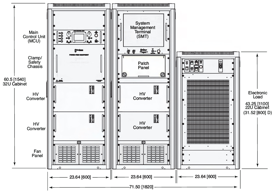
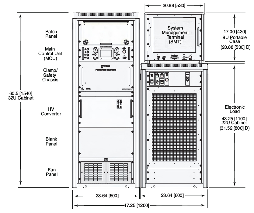
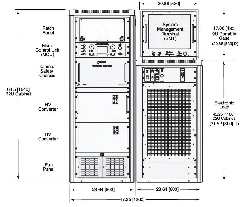
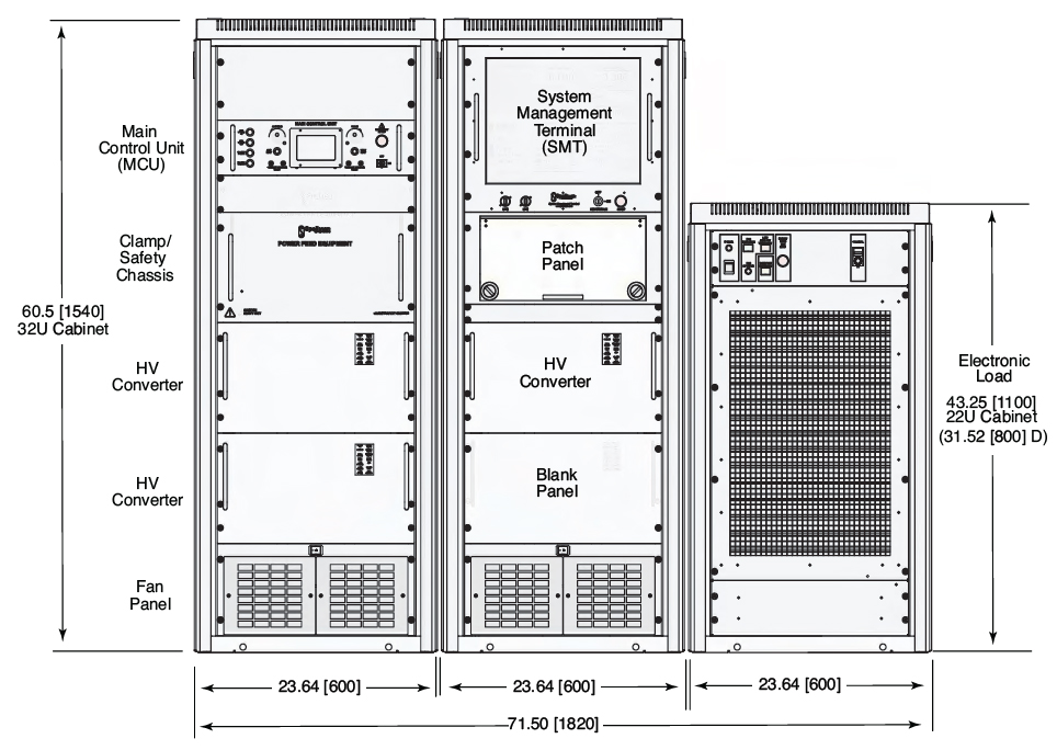
Clamp/Safety Chassis:
Protects the repeaters/cable and PFE. A HV relay and dump circuit will quickly and safely discharge the system in case of emergency shutdown. A front panel mounted lamp indicates if the PFE output is energized.
Output Control:
Using either the Main Control Unit (MCU) or SMT; the system output can be operated in constant current or constant voltage control and as a feed for a single end, double end or branched line.
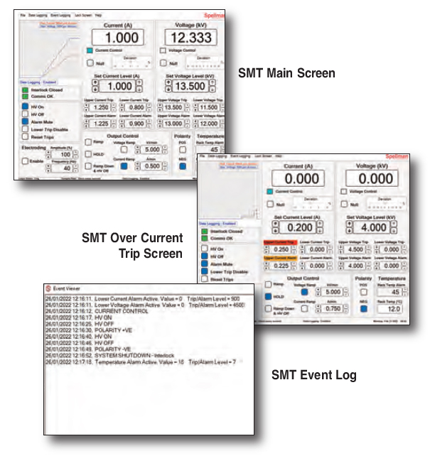
 System Management Terminal (SMT):
The SMT is an advanced touchscreen control and monitoring system which can be installed within the PFE cabinets or remotely up to 80m from the PFE.
- Full output control and monitoring
- Fully adjustable ramp rates in current or voltage control: 10V-10kV/min and 10mA-10A/min
- User settable over/under voltage and current trips and alarms
- Output voltage and current logging
- Event logging
- Programmable electroding (tone generator 10-40Hz provided)
Typical System Management Screens:
Main Control Unit (MCU):
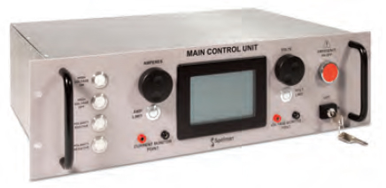 The system can be controlled manually using the MCU front panel controls.
- 4.2” LCD display
- Full output control and monitoring including polarity reversal
- Test points for voltage and current
- Front panel controls for voltage and current
- Ramp rates available: Default: 60kV/min 6A/min. Slow: 500V/min 0.2A/min.
- Over volts/current trips
- HV and Alarm outputs
Patch Panel:
User configurable interconnects from Converter(s) to Electronic Load or Cable Termination Cubicles (CTC’s).
Electronic Load:
Fully isolated and actively adjustable resistance by the user.
Max power: 30kW
Max voltage: ± 15kV @ 2A
Max current: 2.4A @ ±12.5kV
Interlock System:
Full protection for user and connected equipment. All PFE access panels and patch panel connections are interlocked. External connection terminals are provided to allow connection to CTCs, associated equipment or external E-Stop circuits.
Optional Hood (17668-4)
A flange at the rear provides attachment of exhaust ducting, allowing most of the heat dissipated from the system to be transferred outside the immediate environment of the PFE.
Optional Cable Termination Cubicle (CTC12/377)
Facility to safely accommodate half joints and bare cables for installation and repairs. The CTC provides a safe, interlocked enclosure for connection of the PFE HV to the cable conductors. 2 clamps and strain relief allow the fiber core to be separated and safely routed out of the box to external optical equipment.
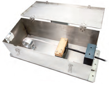
W 27.26˝ [692mm]
D 10.44˝ [265mm]
H 8.27˝ [210mm]
Dimensions: in.[mm]
PFESB6PN12
Weight:
Cabinet 1: 441 lbs. [200kg]
SMT: 33 lbs. [15kg]
Electronic Load: 364 lbs. [165kg]
PFESB10PN24
Weight:
Cabinet 1: 1529 lbs. [240kg]
SMT: 33 lbs. [15kg]
Electronic Load: 364 lbs. [165kg]
Dimensions: in.[mm]
PFESB15PN36
Weight:
Cabinet 1: 507 lbs. [230kg]
Cabinet 2: 309 lbs. [140kg]
Electronic Load: 364lbs. [165kg]
PFESB20PN40
Weight:
Cabinet 1: 507 lbs. [230kg]
Cabinet 2: 419 lbs. [190kg]
Electronic Load: 364lbs. [165kg]