Series PFE - SB
- Versiones disponibles de 6kV a 20kV.
- Carga de prueba electrónica continuamente variable capaz de disipar 30kW.
- Velocidades de rampa ascendente y descendente para voltaje y corriente.
- Funciones de electrodo programables proporcionadas.
- Inversión de polaridad electrónica.
- Funciones de registro de datos y eventos.
- Funciones de alarma y disparo.
*Nota: Todas las especificaciones están sujetas a cambios sin previo aviso. Consulte la versión en PDF en inglés de esta hoja de datos para obtener la revisión más actualizada.
Equipo de alimentación de energía a bordo de buques (PFE)
(Ref. 128144-001 REV. B)
Proporciona todas las características para permitir un funcionamiento seguro y confiable con funciones de configuración que se adaptan a todos los requisitos de instalación de cables. El sistema PFE está diseñado para proporcionar un suministro de alto voltaje bien regulado, de baja ondulación y con diferentes requisitos de corriente.
Un sistema de gestión digital avanzado proporciona configuración de salida, control, ajuste de polaridad, monitoreo continuo e informes de alarma desde la Unidad de Control Principal (MCU) o el Terminal de Administración del Sistema (SMT).
La carga de prueba electrónica es un diseño activo de estado sólido que permite variar dinámicamente la carga utilizando un control manual en el panel frontal.
El sistema se alimenta directamente de una fuente de alimentación de 3 fases sin necesidad de autotransformadores.
SPECIFICATIONS:
PFE-SB—Input/Output
| Model | Output Voltage | Output Current | Input Current | Input Current (per phase max) |
|---|---|---|---|---|
| PFESB6PN12 | 6kV | 2A max | 400Vac 3 phase ±10% 50/60Hz | 25A |
| PFESB10PN24 | 10kV | 2.4A max | 400Vac 3 phase ±10% 50/60Hz | 40A |
| PFESB15PN36 | 15kV | 2.4A max | 400Vac 3 phase ±10% 50/60Hz | 60A |
| PFESB20PN40 | 20kV | 2A max | 400Vac 3 phase ±10% 50/60Hz | 75A |
Input Wiring:
3Φ + Neutral (Star). For a 3Φ supply without a neutral (delta), a single phase 230Vac 10A supply will be required to power the control modules.
Voltage Ripple:
<0.3%
Stability:
Typically <0.25% over any 24 hour period with a temperature range of 0°C to 30°C.
Voltage Regulation:
Load: 0.05% of full voltage for full load change.
Line: +/-0.05% of full voltage +500mV over specified range.
Current Regulation:
Load: 0.05% of full current for any voltage change.
Line: +/-0.05% of full current over specified input range.
Temperature Coefficient:
< 100 ppm/°C
Operating Temperature:
0 to +30°C
Storage Temperature:
-10 to +70°C
Humidity:
0% to 90%, non-condensing
Cooling:
Forced Air. 210 liters/sec (445 cfm) per cabinet, 1500 liters/sec (3180 cfm) for the test load.
Regulatory Approvals:
Designed to meet IEC/UL 61010-1 Safety requirements for electrical equipment for measurement, control and laboratory use; CAN/CSA-C22.2 No.61010-1.
KEY FEATURES:
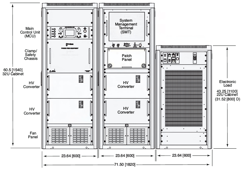
Clamp/Safety Chassis:
Protects the repeaters/cable and PFE. A HV relay and dump circuit will quickly and safely discharge the system in case of emergency shutdown. A front panel mounted lamp indicates if the PFE output is energized.
Output Control:
Using either the Main Control Unit (MCU) or SMT; the system output can be operated in constant current or constant voltage control and as a feed for a single end, double end or branched line.
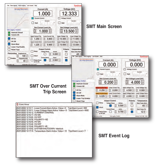
 System Management Terminal (SMT):
The SMT is an advanced touchscreen control and monitoring system which can be installed within the PFE cabinets or remotely up to 80m from the PFE.
- Full output control and monitoring
- Fully adjustable ramp rates in current or voltage control: 10V-10kV/min and 10mA-10A/min
- User settable over/under voltage and current trips and alarms
- Output voltage and current logging
- Event logging
- Programmable electroding (tone generator 10-40Hz provided)
Typical System Management Screens:
Main Control Unit (MCU):
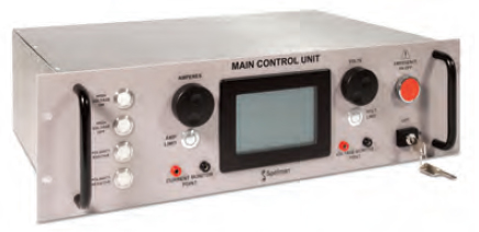 The system can be controlled manually using the MCU front panel controls.
- 4.2” LCD display
- Full output control and monitoring including polarity reversal
- Test points for voltage and current
- Front panel controls for voltage and current
- Ramp rates available: Default: 60kV/min 6A/min. Slow: 500V/min 0.2A/min.
- Over volts/current trips
- HV and Alarm outputs
Patch Panel:
User configurable interconnects from Converter(s) to Electronic Load or Cable Termination Cubicles (CTC’s).
Electronic Load:
Fully isolated and actively adjustable resistance by the user.
Max power: 30kW
Max voltage: ± 15kV @ 2A
Max current: 2.4A @ ±12.5kV
Interlock System:
Full protection for user and connected equipment. All PFE access panels and patch panel connections are interlocked. External connection terminals are provided to allow connection to CTCs, associated equipment or external E-Stop circuits.
Optional Hood (17668-4)
A flange at the rear provides attachment of exhaust ducting, allowing most of the heat dissipated from the system to be transferred outside the immediate environment of the PFE.
Optional Cable Termination Cubicle (CTC12/377)
Facility to safely accommodate half joints and bare cables for installation and repairs. The CTC provides a safe, interlocked enclosure for connection of the PFE HV to the cable conductors. 2 clamps and strain relief allow the fiber core to be separated and safely routed out of the box to external optical equipment.
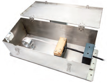
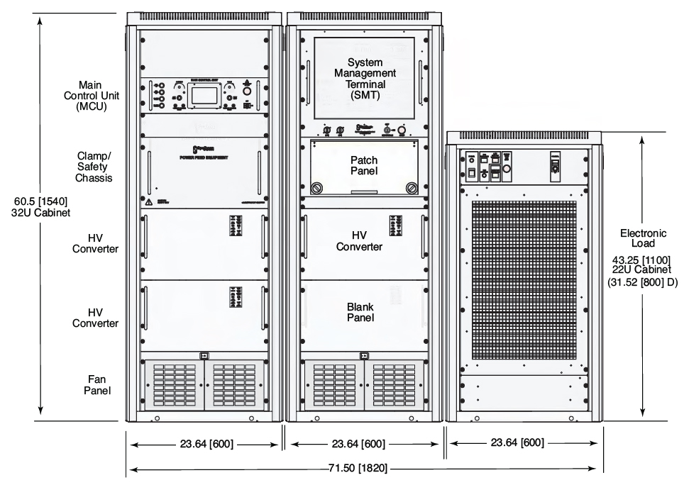
W 27.26˝ [692mm]
D 10.44˝ [265mm]
H 8.27˝ [210mm]
Dimensions: in.[mm]
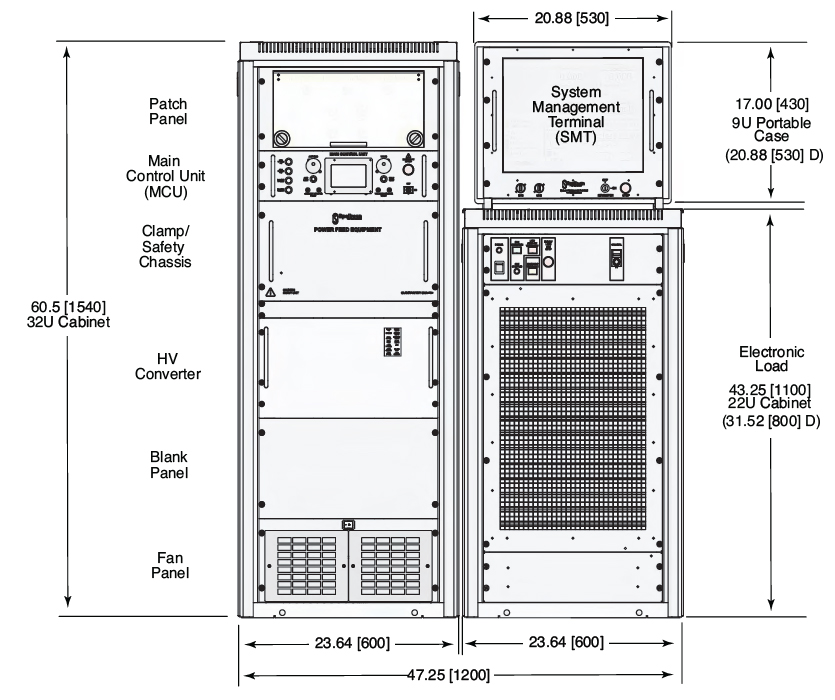
PFESB6PN12
Weight:
Cabinet 1: 441 lbs. [200kg]
SMT: 33 lbs. [15kg]
Electronic Load: 364 lbs. [165kg]
PFESB10PN24
Weight:
Cabinet 1: 1529 lbs. [240kg]
SMT: 33 lbs. [15kg]
Electronic Load: 364 lbs. [165kg]
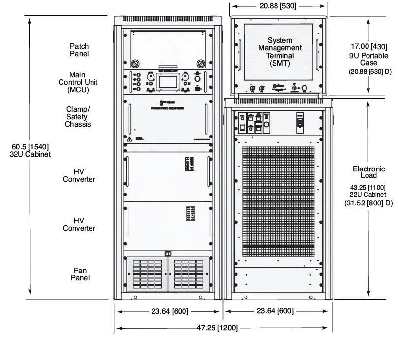
Dimensions: in.[mm]
PFESB15PN36
Weight:
Cabinet 1: 507 lbs. [230kg]
Cabinet 2: 309 lbs. [140kg]
Electronic Load: 364lbs. [165kg]
PFESB20PN40
Weight:
Cabinet 1: 507 lbs. [230kg]
Cabinet 2: 419 lbs. [190kg]
Electronic Load: 364lbs. [165kg]