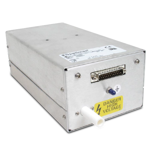
CZE2000
- コスト効果の高いもジュール式電源、 エレクトロスピニングに最適
- 0-30kV. 0-300µA; ローカルまたはリモートプログラミング
- 極性はコマンドにより、無負荷時に1秒未満で逆転可能
- 低貯蔵エネルギー、電流制限出力
*注: すべての仕様は予告なく変更される場合があります。最新版についてはこのデータシートの英語PDF版をご覧ください。


CZE2000 自動極性逆転モジュール式高電圧電源 | スペルマン高電圧電源
CZE2000モジュール型高圧電源は、OEMでの使用に理想的 です。特に、ホット・スイッチ・リバーシブル出力電圧が必要と されるアプリケーションのニーズに対応できるよう設計されてい ます。出力極性は、インターフェース・コネクタに供給される極 性制御信号を介して、素早く安全に変換可能です。
出力電圧と電流はそれぞれ、グランド・リファレンス・プログ ラミング信号を介して完全調節可能で、その結果、0~+10Vdc が0~100%の定格出力電圧および電流に対応できるよう設計 されています。
電圧および電流のテスト・ポイントによるリモート動作機能を 備え、0~10Vdcが0~100%の定格電圧および電流に対応で きるよう設計されています。加えて、極性・モードのリモートイ ン ケータにより、電源装置の運転を総合的に監視できます。
卓越した負荷変動率および入力変動率の仕様は、抜群の安定性 と低リップルと相まって、一貫したプロセスのために必要な安定 した高圧出力を保証します。
用途
- 静電紡糸
- 質量分析
- 電気泳動装置
- 静電気調査
![]()
Specifications
(Ref. 128076-001 REV. L)
Input Voltage:
24Vdc, ±10%
Input Current:
Less than 1 amp
Efficiency:
75% typical
Output Voltage:
See selection table
Output Current:
See selection table
Polarity:
Auto reversible via command
Power:
10 watts, maximum
Line Regulation:
0.01% for a 10% input voltage change
Load Regulation:
0.01% for a full load change
Ripple:
0.1% Vp-p
Stability:
0.02% per 8 hours (after 1/2 hr warmup)
NL Time Constant:
100ms
Stored Energy:
0.2 Joules at 30kV
Temperature Coefficient:
100ppm/°C
Operating Temperature:
0°C to 40°C
Storage Temperature:
-40°C to 85°C
Humidity:
10% to 85% RH, non condensing
Cooling:
Convection cooled
Dimensions:
3.5”H x 5”W x 10”D (8.9cm x 12.7cm x 25.4cm).
Weight:
6.2lbs. (2.8kg)
Interface Connector:
25 pin male D connector
HV Output Connector:
Detachable 36. (0.91m) cable provided
Regulatory Approvals:
Compliant to EEC EMC Directive. Compliant to EEC Low Voltage Directive. UL/CUL recognized file E148969. RoHS Compliant.
CZE2000 SELECTION TABLE
| Maximum Rating | Model Number | |
|---|---|---|
| kV | mA | |
| 5 | 2.0 | CZE5PN2000 |
| 10 | 1.0 | CZE10PN2000 |
| 15 | 0.67 | CZE15PN2000 |
| 20 | 0.50 | CZE20PN2000 |
| 30 | 0.30 | CZE2000 |
CZE2000 25 PIN MALE D CONNECTOR
| Pin | Signal | Parameters |
|---|---|---|
| 1 | +24Vdc Return | Power Return |
| 2 | +24Vdc Return | Power Return |
| 3 | +24Vdc Return | Power Return |
| 4 | HV Enable/Inhibit | Open or <1Vdc = HV OFF, >3.4Vdc (up to 15Vdc) = HV ON1 |
| 5 | Voltage Test Point | 0 to 10Vdc = 0 to 100% rated output, Zout =10kΩ, 1% |
| 6 | Current Test Point | 0 to 10Vdc = 0 to 100% rated output, Zout =10kΩ, 1% |
| 7 | Chassis Ground | Ground |
| 8 | Remote Voltage Control | 0 to 10Vdc = 0 to 100% Rated Output, Zin =10MΩ |
| 9 | Remote Current Control | 0 to 10Vdc = 0 to 100% Rated Output, Zin =10MΩ |
| 10 | +10Vdc Reference Output | +10Vdc, 4mA maximum |
| 11 | Signal Return | Signal Return |
| 12 | Polarity Control | Open or >3.4Vdc (up to 15Vdc) = Positive Polarity. Grounded or <1Vdc = Negative Polarity |
| 13 | Positive Polarity Indicator | +24Vdc sourced through a 100Ω series limiting resistor. +24Vdc = active signal |
| 14 | +24Vdc Input | Power Input |
| 15 | +24Vdc Input | Power Input |
| 16 | Chassis Ground | Ground |
| 17 | Negative Polarity Indicator | +24Vdc sourced through a 100Ω series limiting resistor. +24Vdc = active signal |
| 18 | I Mode Indicator | Open collector pulled up internally to +15Vdc through 2.7kΩ resistor with a 470Ω limiting resistor in series. Transistor OFF = signal active |
| 19 | V Mode Indicator | Open collector pulled up internally to +15Vdc through 2.7kΩ resistor with a 470Ω limiting resistor in series. Transistor OFF = signal active |
| 20 | Return Current Test Point | 0 to 10Vdc = 0 to 100% rated output current, as measured returned from load. Zout =10kΩ, 1% |
| 21 | Load Return | High Voltage Return Point. Required for GFI circuit functionality |
| 22 | Ground Fault Indicator | Open collector pulled up internally to +15Vdc through 4.7kΩ resistor with a 470Ω limiting resistor in series. Transistor OFF = signal active |
| 23 | Spare | No Connection |
| 24 | Spare | No Connection |
| 25 | Spare | No Connection |
Tables & Diagrams
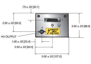
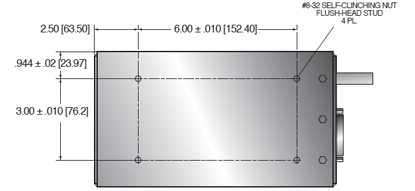
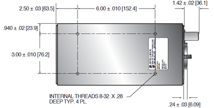
DIMENSIONS: in.[mm]
FRONT VIEW
TOP VIEW
BOTTOM VIEW
Frequently Asked Questions
What Is a Safe Level of High Voltage?
Where Can I Obtain Information on High Voltage Safety Practices?
How Should I Ground Your Supply?

