SERIE CZE2000
- Fuente modular rentable; ideal para el electrohilado
- Programación local o remota de 0 kV-30 kV y 0 µA-300 µA.
- Inversión de polaridad a solicitud en <1 segundo sin carga
- Bajo almacenamiento de energía, salida limitada de corriente


*Nota: Todas las especificaciones están sujetas a cambios sin previo aviso. Consulte la versión en PDF en inglés de esta hoja de datos para obtener la revisión más actualizada.
FUENTE DE ALIMENTACIÓN DE ALTO VOLTAJE DE INVERSIÓN AUTOMÁTICA
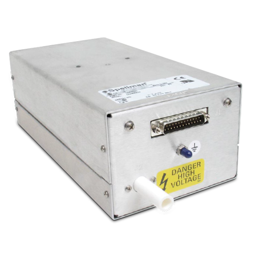
La fuente modular de alimentación de energía de alto voltaje CZE2000 de Spellman es ideal para uso en aplicaciones de OEM. Está específicamente diseñada para cumplir las necesidades de las aplicaciones que requieren voltaje de salida con inversión sin desconexión. La polaridad de salida de la unidad puede invertirse de forma segura y rápida mediante la señal de control de polaridad suministrada en el conector de la interfaz.
El voltaje y la corriente de salida se ajustan por completo mediante señales de programación remotas con referencia a tierra tales como 0 VCD a 10 VCD que corresponde a 0 a 100% del voltaje y corriente de salida nominales.
La funcionalidad para la indicación remota se proporciona mediante puntos de prueba de voltaje y corriente tales como, 0 VCD a 10 VCD que corresponde a 0 a 100% del voltaje y la corriente nominal. Adicionalmente los indicadores remotos de polaridad y modo proporcionan una vista general detallada de la operación de la fuente de energía.
Las excelentes especificaciones de regulación de línea y carga, además de la sorprendente estabilidad y bajo rizo aseguran una salida de alto voltaje estable para resultados consistentes de los procesos.
Typical applications:
- Electrohilado
- Espectrometría de masas
- Electroforesis capilar
- Investigación electrostática
![]()
Especificaciones
(Ref. 128076-001 REV. L)
Input Voltage:
24Vdc, ±10%
Input Current:
Less than 1 amp
Efficiency:
75% typical
Output Voltage:
See selection table
Output Current:
See selection table
Polarity:
Auto reversible via command
Power:
10 watts, maximum
Line Regulation:
0.01% for a 10% input voltage change
Load Regulation:
0.01% for a full load change
Ripple:
0.1% Vp-p
Stability:
0.02% per 8 hours (after 1/2 hr warmup)
NL Time Constant:
100ms
Stored Energy:
0.2 Joules at 30kV
Temperature Coefficient:
100ppm/°C
Operating Temperature:
0°C to 40°C
Storage Temperature:
-40°C to 85°C
Humidity:
10% to 85% RH, non condensing
Cooling:
Convection cooled
Dimensions:
3.5”H x 5”W x 10”D (8.9cm x 12.7cm x 25.4cm).
Weight:
6.2lbs. (2.8kg)
Interface Connector:
25 pin male D connector
HV Output Connector:
Detachable 36. (0.91m) cable provided
Regulatory Approvals:
Compliant to EEC EMC Directive. Compliant to EEC Low Voltage Directive. UL/CUL recognized file E148969. RoHS Compliant.
CZE2000 SELECTION TABLE
| Maximum Rating | Model Number | |
|---|---|---|
| kV | mA | |
| 5 | 2.0 | CZE5PN2000 |
| 10 | 1.0 | CZE10PN2000 |
| 15 | 0.67 | CZE15PN2000 |
| 20 | 0.50 | CZE20PN2000 |
| 30 | 0.30 | CZE2000 |
CZE2000 25 PIN MALE D CONNECTOR
| Pin | Signal | Parameters |
|---|---|---|
| 1 | +24Vdc Return | Power Return |
| 2 | +24Vdc Return | Power Return |
| 3 | +24Vdc Return | Power Return |
| 4 | HV Enable/Inhibit | Open or <1Vdc = HV OFF, >3.4Vdc (up to 15Vdc) = HV ON1 |
| 5 | Voltage Test Point | 0 to 10Vdc = 0 to 100% rated output, Zout =10kΩ, 1% |
| 6 | Current Test Point | 0 to 10Vdc = 0 to 100% rated output, Zout =10kΩ, 1% |
| 7 | Chassis Ground | Ground |
| 8 | Remote Voltage Control | 0 to 10Vdc = 0 to 100% Rated Output, Zin =10MΩ |
| 9 | Remote Current Control | 0 to 10Vdc = 0 to 100% Rated Output, Zin =10MΩ |
| 10 | +10Vdc Reference Output | +10Vdc, 4mA maximum |
| 11 | Signal Return | Signal Return |
| 12 | Polarity Control | Open or >3.4Vdc (up to 15Vdc) = Positive Polarity. Grounded or <1Vdc = Negative Polarity |
| 13 | Positive Polarity Indicator | +24Vdc sourced through a 100Ω series limiting resistor. +24Vdc = active signal |
| 14 | +24Vdc Input | Power Input |
| 15 | +24Vdc Input | Power Input |
| 16 | Chassis Ground | Ground |
| 17 | Negative Polarity Indicator | +24Vdc sourced through a 100Ω series limiting resistor. +24Vdc = active signal |
| 18 | I Mode Indicator | Open collector pulled up internally to +15Vdc through 2.7kΩ resistor with a 470Ω limiting resistor in series. Transistor OFF = signal active |
| 19 | V Mode Indicator | Open collector pulled up internally to +15Vdc through 2.7kΩ resistor with a 470Ω limiting resistor in series. Transistor OFF = signal active |
| 20 | Return Current Test Point | 0 to 10Vdc = 0 to 100% rated output current, as measured returned from load. Zout =10kΩ, 1% |
| 21 | Load Return | High Voltage Return Point. Required for GFI circuit functionality |
| 22 | Ground Fault Indicator | Open collector pulled up internally to +15Vdc through 4.7kΩ resistor with a 470Ω limiting resistor in series. Transistor OFF = signal active |
| 23 | Spare | No Connection |
| 24 | Spare | No Connection |
| 25 | Spare | No Connection |
Tablas y Diagramas
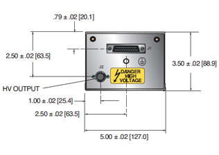
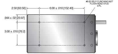
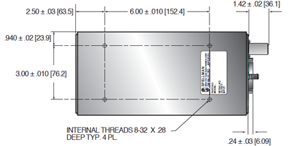
DIMENSIONS: in.[mm]
FRONT VIEW
TOP VIEW
BOTTOM VIEW
Frequently Asked Questions
What Is a Safe Level of High Voltage?
Where Can I Obtain Information on High Voltage Safety Practices?
How Should I Ground Your Supply?

