")
ST Series
- Single 6U (10.5”) Chassis
- Models from 1kV to 225kV
- Remote Analog and Remote Ethernet Interface
- Parallel Units for >100kW’s
- User Configurable Settings Via Ethernet Interface
*Note: All specifications are subject to change without notice. Please consult the English PDF version of this datasheet for the most up-to-date revision.


12kW High Voltage Power Supplies
Spellman’s ST Series of 12kW high voltage power supplies are available in positive or negative polarities in 20 different models with outputs ranging from 1kV to 225kV. A full featured front panel allows easy local control, while an extensive analog interface provides comprehensive remote capability. The standard Ethernet and RS-232 digital interfaces simplify integrating the ST into your system design.
The ST’s robust IGBT inverter is inherently fault tolerant and is ideal for demanding applications like semiconductor processing and vacuum deposition. Many operational features can be configured by the user to suit their particular requirements. Power >100kW’s can be provided by configuring additional chassis in parallel.
Typical applications:
- Ion Beam Implantation
- Semiconductor Processing
- Electron Beam Welding
- Capacitor Charging
- High Power RF Transmitters
- Electrostatic Precipitators
- X Ray Systems
Specifications
(Ref. 128077-001 REV. V)
SPECIFICATIONS
Input Voltage:
Standard: 180-264Vac, 50/60Hz, three phase, 90% efficiency, 0.85 power factor
Optional: 360-528Vac 50/60Hz, three phase (400Vac)
Input Current:
Standard: 180-264Vac, three phase; 50 amps, maximum
Optional: 360-528Vac, three phase; 25 amps, maximum
Output Voltage:
20 models from 1kV to 225kV. Each model is available with positive or negative outputs. 1kV to 10kV units are internally reversible.
Local Output Controls:
Voltage and current are continuously adjustable over entire range via ten-turn potentiometers with lockable counting dials.
Voltage Regulation:
Load: 0.05% of full voltage +500mV for full load change.
Line: 0.05%of full voltage +500mV over specified input range.
Current Regulation:
Load: 0.05% of full current ±100µA for any voltage change.
Line: 0.05% of full current over specified input range.
Ripple:
0.3% p-p +1Vrms. Lower ripple available via special order
Stability:
0.02%hr. after 1 hour warm-up.
Temperature Coefficient:
100ppm/°C. Higher stability (50ppm/°C) available on special order via the HS option
Environmental:
Temperature Range:
Operating: 0°C to 40°C
Storage: -40°C to 85°C
Humidity: 10% to 90% RH, non-condensing.
Cooling:
Forced air; inlet through side panels, outlet at rear panel
Metering:
Digital voltage and current meters, accurate to within 1%
System Status Display:
“Dead Front” type indicators provide status of up to 12 system operations including voltage and current regulation, fault conditions and circuit control.
Digital Interface:
Ethernet and RS-232 digital interface implemented with 12 bits of resolution. A VB GUI is provided.
Input Line Connector:
A 6 foot (1.8 meter) long captive line cord is provided.
Analog Interface Connector:
50 pin female D connector
High Voltage Output Cable:
1-150kV: A detachable 10’ (3.05m) long shielded HV cable is provided
225kV: R-28 type X-Ray connector. No output cable is provided
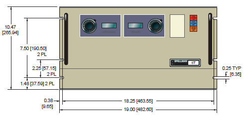
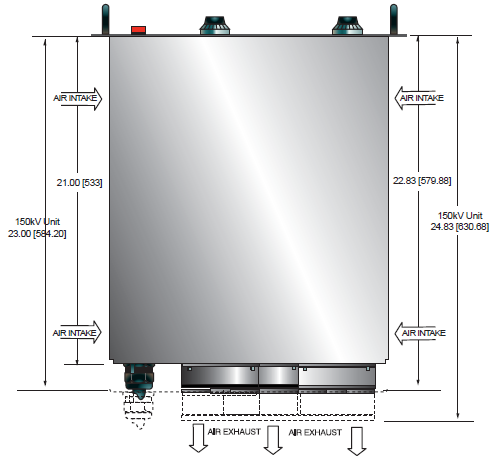
Dimensions:
10.5˝ (6U)H X 19˝ W X 21˝ D (266mm x 482mm x 533mm)
150kV: 10.5˝ (6U)H X 19˝ W X 23˝ D (266mm x 482mm x 584mm)
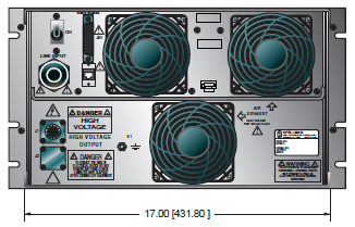
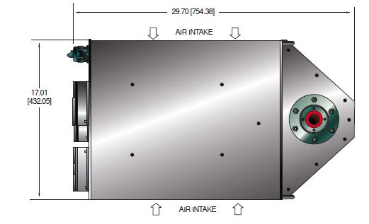
225kV: 20.55˝ H X 17.01˝ W X 29.7˝ D (521mm x 432mm x 754mm)
Weight:
1kV to 50kV: <100 pounds (45.36kg)
60kV to 120kV: <140 pounds (63.50kg)
150kV: <150 pounds (68.03kg)
225kV: <260 pounds (117.9kg)
Individual kV models may vary
Regulatory Approvals:
Compliant to EEC EMC Directive. Compliant to EEC Low Voltage Directive. RoHS Compliant.
Digital Interface
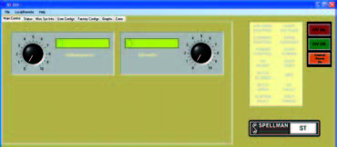
The ST features a standard RS-232 and Ethernet digital interface. Utilizing these standard digital interfaces can dramatically simplify power supply interfacing requirements saving the user both time and money, while enhancing functionality and overall capability. Spellman provides a GUI with the ST that allows the customer to both customize operational features of the ST while also providing basic power supply operational features. Details of the ST’s digital interface capability are described in detail in the ST manual, downloadable via the link on the first page of this data sheet.
Main control screen
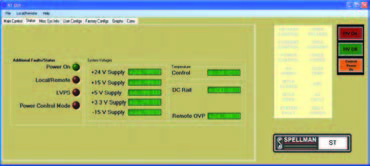
Status screen
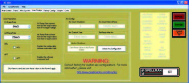
User configuration screen
Parallel Capability
The ST series is designed to offer additional power capability by adding a chassis in parallel to create a main/secondary configuration providing up to and beyond 100kW’s. The main chassis is the point of connection for customer interfacing; this multichassis system effectively functions as a single power supply. The main unit retains the full featured front panel, while secondary units have a Blank Front Panel. To configure an orderable model number, simply use Spellman’s applicable base ST model number and increment the power denominator in 12kW steps as required:
ST60P24
This would be an ST with a 60kV, positive polarity, providing 24kW’s of power (2 chassis)
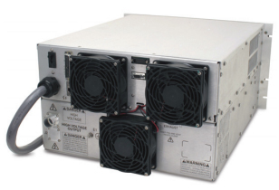
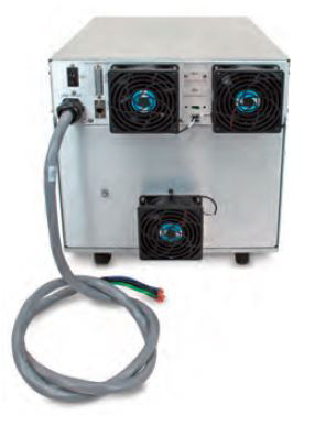
Rear panel showing connections for parallel operation:
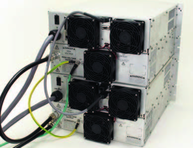
Rear panel showing connections for parallel operation
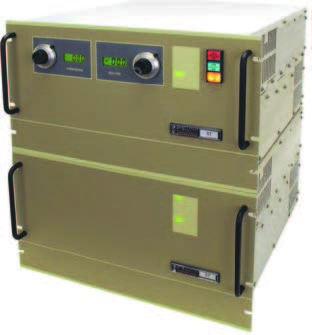
Main/secondary 24kW ST
Arc Intervention
Spellman’s ST power supplies have an arc intervention feature that senses arc currents via a fast acting current sense transformer. The purpose of the arc intervention circuitry is to prevent power supply damage from continuous, long term arcing. The factory default configuration will trip off the unit with an Arc Fault if 4 arcs occur in a 10 second time period. Customers can change basic arc intervention parameters (Arc Count, Arc Quench, Reramp Time, and Window Time) within preset limits via the digital interface; customized units can be provided for unique arc prone environments, contact Spellman for details.
HARDWARE BASED OPTIONS
BFP - Blank Front Panel
HS - High Stability
LL(X) - High Voltage Cable Length
400VAC - 360-528Vac Input
SOFTWARE CONFIGURABLE FEATURES
Adjustable Overload Trip
Arc Trip Count
Arc Quench Time
Arc Re-Ramp Time
Constant Power Control
Adjustable Power Trip
Slow Start Ramp Times
Electronic Component (Power Source)
ST series is intended for installation as a component of a system. It is designed to meet CE standards, with conditions of acceptance often being: customer provided enclosure mounting, EMC filtering, and appropriate protection, and isolation devices. The ST series is not intended to be operated by end users as a stand-alone device. The ST series power supply can only be fully assessed when installed within a system, and as a component part within that system.
ST SELECTION TABLE
| Maximum Rating | Model Number | |
|---|---|---|
| kV | mA | |
| 1 | 12,000 | ST1*12 |
| 2 | 6,000 | ST2*12 |
| 3 | 4,000 | ST3*12 |
| 4 | 3,000 | ST4*12 |
| 6 | 2,000 | ST6*12 |
| 8 | 1,500 | ST8*12 |
| 10 | 1,200 | ST10*12 |
| 12 | 1,000 | ST12*12 |
| 15 | 800 | ST15*12 |
| 20 | 600 | ST20*12 |
| 30 | 400 | ST30*12 |
| 40 | 300 | ST40*12 |
| 50 | 240 | ST50*12 |
| 60 | 200 | ST60*12 |
| 70 | 171 | ST70*12 |
| 80 | 150 | ST80*12 |
| 100 | 120 | ST100*12 |
| 120 | 100 | ST120*12 |
| 150 | 67 | ST150*10 |
| 225 | 40 | ST225*10 |
*Substitute “P” for positive polarity and “N” for negative polarity. Polarity must be specified at time of order. 1-10kV units are inherently reversible by design requiring an internal wiring change to swap polarities. Intermediate voltage units are available by special order. 150kV units are limited to a maximum output of 10kW’s
NOTE: ST225 units cannot be paralled!
Parallel operation: Additional power can be provided in increments of 12kW’s by connecting chassis in parallel via the use of the ST’s main/secondary configuration.
Use the applicable base ST model number and increment the power denominated in 12kW steps as required.
ST10P24 10kV @ 24kW’s
ST10P36 10kV @ 36kW’s
ST10P48 10kV @ 48kW’s
ST 1-150kV rear panel view
ST 225V rear panel view
JB1 ST ANALOG INTERFACE—50 PIN FEMALE D CONNECTOR
| Pin | Signal | Parameters |
|---|---|---|
| 1 | Power Supply Common | Power Supply Ground |
| 2 | Reset/HV Inhibit | Normally open, Low = Reset/Inhibit |
| 3 | External Interlock | +24Vdc @ open, <25mA @ closed |
| 4 | External Interlock Return | Return for External Interlock |
| 5 | mA Test Point | 0-10Vdc = 0-100% rated output, Zout= 1KΩ, 1% |
| 6 | kV Test Point | 0-10Vdc = 0-100% rated output, Zout= 1KΩ, 1% |
| 7 | +10Vdc Reference Output | +10Vdc @ 1mA |
| 8 | mA Program Input | 0-10Vdc = 0-100% rated output, Zin>10MΩ |
| 9 | Local mA Program Output | 0-10Vdc = 0-100% rated output, front panel pot |
| 10 | kV Program Input | 0-10Vdc = 0-100% rated output, Zin>10MΩ |
| 11 | Local kV Program Output |
010Vdc = 0100% rated output, front panel pot |
| 12 | Remote Power On Output |
+24Vdc @ open, 2A peak, 1Adc @ closed |
| 13 | Remote Power On Return |
Return for Remote Power On |
| 14 | Remote HV Off | +24Vdc @ open, 2A peak, 1Adc @ closed, connect to pin15 for front panel operation |
| 15 | Remote HV Off/On Common |
HV On/Off Common |
| 16 | Remote HV On | +24Vdc @ open, 2A peak, 1Adc @ closed, momentarily connect to pin 15 enable high voltage |
| 17 | HV Off Indicator |
+24Vdc @ 25mA = HV Off |
| 18 | HV On Indicator | +24Vdc @ 25mA = HV On |
| 19 | Power Supply Common |
Supply Ground |
| 20 | +24Vdc Output | +24Vdc @ 100mA, maximum |
| 21 | Voltage Mode Status | Open Collector, Low = Active |
| 22 | Current Mode Status | Open Collector, Low = Active |
| 23 | Power Mode Status | Open Collector, Low = Active |
| 24 | Interlock Closed Status | Open Collector, Low = Active |
| 25 | Power Test Point | 010Vdc = 0100% rated output, Zout= 5KΩ, 1% |
| 26 | Spare | |
| 27 | Spare | |
| 28 | Remote Overvoltage Adjust |
010Vdc = 0100% rated output |
| 29 | Over Power Fault | Open Collector, Low = Active |
| 30 | Over Voltage Fault | Open Collector, Low = Active |
| 31 | Over Current Fault | Open Collector, Low = Active |
| 32 | System Fault | Open Collector, Low = Active |
| 33 | RGLT Error Fault | Open Collector, Low = Active |
| 34 | Arc | Open Collector, Low = Active |
| 35 | Over Temp Fault | Open Collector, Low = Active |
| 36 | AC Fault | Open Collector, Low = Active |
| 37 | Spare | |
| 38 | Spare | |
| 39 | Spare | |
| 40 | Spare | |
| 41 | Spare | |
| 42 | Remote Power Program Input | 010Vdc = 0100% rated output, Zin>10MΩ |
| 43 | Local Power Program Output |
010Vdc = 0100% rated output, internal pot |
| 44 | +5Vdc Output | +5Vdc @ 100mA, maximum |
| 45 | +15Vdc Output | +15Vdc @ 100mA, maximum |
| 46 | 15Vdc Output | 15Vdc @ 10mA, maximum |
| 47 | RS232 Tx | |
| 48 | RS232 Rx | |
| 49 | RS232 GND | |
| 50 | Power Supply Common | Power Supply Ground |
Tables & Diagrams
DIMENSIONS: in.[mm]
ST 1kV-150kV
FRONT VIEW
TOP VIEW
BACK VIEW
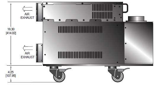
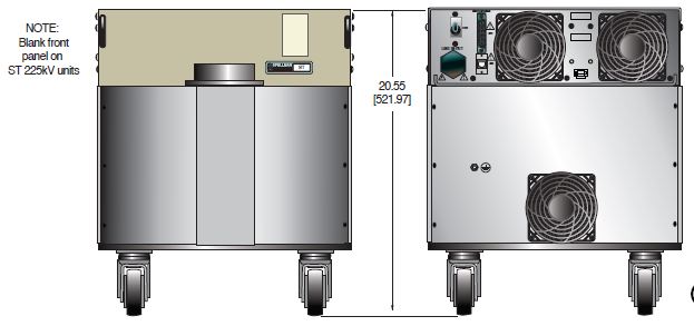
DIMENSIONS: in.[mm]
ST 225kV
TOP VIEW
SIDE VIEW
FRONT VIEW REAR VIEW
Frequently Asked Questions
What Is a Safe Level of High Voltage?
What Is an “External Interlock”?
Where Can I Obtain Information on High Voltage Safety Practices?
What Do You Mean That the Output Side of the High Voltage Cable on Most Standard Products Is “Unterminated”?
How Should I Ground Your Supply?
Why Is Arcing an Issue for a High Voltage Power Supply?
Application Notes AN-13 – Arc Intervention Circuitry and External Series Limiting Resistors
Application Notes AN-14 – The Limits of Front Panel Digital Meters
Application Notes AN-15 – 3.5 And 4.5 Digit Meter Displays Explained
Application Notes AN-16 – Parallel Capability of the St Series
Application Notes AN-18 – Current Loop/Arc Detection Circuitry
Application Notes AN-19 – High Voltage Cable Lengths Discussed

