DXBシリーズ
- ひとつのユニットでバイポーラ出力
- 小型軽量
- モデル種類: 40kV~320kV、300W、600W、1200W
- ユニバーサル入力、力率改善
- USB、イーサネット、RS-232 標準インターフェイス
- CE準拠、UL認証
*注: すべての仕様は予告なく変更される場合があります。最新版についてはこのデータシートの英語PDF版をご覧ください。

![]()
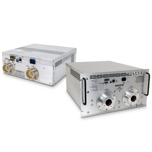
産業用X線ジェネレーター DXBシリーズ 300~1200W
スペルマンの新しいDXBシリーズのバイポーラX線発生モジュールはOEMアプリケーション用で、最高320kV (±160kV)、1200W出力です。ユニバーサル入力、小さなパッケージ、3種の標準デジタルインターフェイスで、DXBをX線分析システムへの統合が容易です。DSPベースの放射制御回路は放射電流の優れた制御を、卓越した安定性と共に提供します。
典型的な用途:
- プラスチックの仕分け
- 結晶検査
- メッキ測定
- 厚みゲージ
- 食品検査
- 鉱物分析
- 蛍光X線
- X線回折
- 貨物スクリーニング
Specifications
(Ref. 128100-001 REV. N)
Input Voltage:
Power factor corrected input
100-240Vac, ±10% (90-264Vac):
47-63Hz @ 5.7A for 300 watt units
200-240Vac, ±10% (180-264Vac):
47-63Hz @ 4.8A for 600 watt units
47-63Hz @ 8.0A for 1200 watt units
Output Voltage:
7 models: 40kV, 60kV, 80kV, 100kV, 120kV, 140kV and 320kV
Output Polarity:
± bipolar output, filament referenced to negative output
Power:
3 power ranges available—300 watts, 600 watts
and 1200 watts
Other power levels available on special order.
Output Voltage Regulation:
≤ 0.01% of rated output voltage over specified input voltage range
≤ 0.01% of rated output voltage for a full load change
Emission Current Regulation:
≤ 0.01% of rated output current over specified input voltage range
≤ 0.01% of rated output current for a change from 30% to 100% of rated output voltage
Filament is disabled when kV is <30% of full scale output
Ripple:
≤ 1%rms at >20 kHz, 0.1%rms below 20 kHz
Stability:
≤ 25ppm/hr after a 2 hour warm up
Temperature Coefficient:
≤ 50ppm per degree C
Environmental:
Temperature Range:
Operating: 0°C to 40°C
Storage: -40°C to 85°C
Humidity:
20% to 85% RH, non-condensing.
Filament Configuration:
Closed loop emission control regulates filament setting to provide desired X-Ray tube emission current.
Floating Filament (ac output referenced to negative output voltage).
Output:
0-5 amps at a compliance of 10 volts, maximum. The filament loop is disabled when the kV output is less than 30% of full scale output to protect the X-Ray tube. Other filament levels available on special order.
Control Interface
Local Interface: Potentiometers are provided to adjust filament limit and preheat levels
Remote Interface: USB, Ethernet and RS-232 are standard. All digital monitors have an accuracy specification of 2%
Control Software: A Windows graphical user interface example is provided.
High Voltage Enable: A hardware based, dry contact closure will enable the power supply into the high voltage on mode
Monitor Signals: Voltage and current monitor signals are scaled 0-10Vdc equals 0-100% of full scale, accuracy is 1%
Cooling:
Forced air
Dimensions:
40-140kV:
4.75˝ H X 12˝ W X 12˝ D (120.65mm x 304.8mm x 304.8mm)
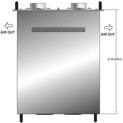
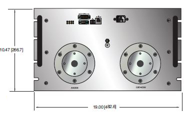
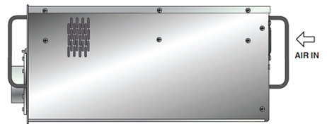
320kV:
10.5˝ H X 19.0˝ W X 21.5˝ D (266.7mm x 482.6mm x 546.1mm)
Weight:
40-140kV: 26 pounds (11.8kg)
320kV: 150 pounds (68kg)
Input Line Connector:
IEC320 with EMI filter
Output Connectors:
40-140kV:
Claymount Mini Federal Standard X-Ray connectors.
Other connectors and pinouts available on special order.
320kV:
R24 X-Ray connectors.
Other connectors and pinouts available on special order.
Regulatory Approvals:
Compliant to EEC EMC Directive. Compliant to EEC Low Voltage Directive. UL/CUL recognized, File E227588. RoHS Compliant. DXB320PN1200 is not UL recognized.
DXB SELECTION TABLE— 300W, 600W, 1200W
| 300 Watt | 600 Watt | 1200 Watt | ||||
|---|---|---|---|---|---|---|
| kV | mA | Model | mA | Model | mA | Model |
| 40 | 7.50 | DXB40PN300 | 15.0 | DXB40PN600 | 30.0 | DXB40PN1200 |
| 50 | 5.00 | DXB60PN300 | 10.0 | DXB60PN600 | 20.0 | DXB60PN1200 |
| 80 | 3.75 | DXB80PN300 | 7.50 | DXB80PN600 | 15.0 | DXB80PN1200 |
| 100 | 3.00 | DXB100PN300 | 6.00 | DXB100PN600 | 12.0 | DXB100PN1200 |
| 120 | 2.50 | DXB120PN300 | 5.00 | DXB120PN600 | 10.0 | DXB120PN1200 |
| 140 | 2.14 | DXB140PN300 | 4.28 | DXB140PN600 | 8.57 | DXB140PN1200 |
| 320 | Not Available | Not Available | 3.75 | DXB320PN1200 | ||
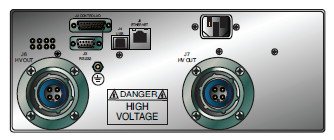
DXB ANALOG INTERFACE— J2 15 PIN MALE D CONNECTOR
| Pin | Signal | Signal Parameters |
|---|---|---|
| 1 | Power Supply Fault | Open Collector, 35V @ 10mA Maximum |
| 2 | Current Program In | 0 to 10V=0 to 100% Rated Output, Zin=10MΩ |
| 3 | Voltage Program In | 0 to 10V=0 to 100% Rated Output, Zin=10MΩ |
| 4 | Filament Limit Input | 0 to 10V=0 to 100% Rated Output, Zin=10MΩ |
| 5 | Local Filament Limit | Multi-turn front panel potentiometer |
| 6 | Filament Preheat Input | 0 to 10V=0 to 100% Rated Output, Zin=10MΩ |
| 7 | Local Filament Preheat | Multi-turn front panel potentiometer |
| 8 | Voltage Monitor | 0 to 10V=0 to 100% Rated Output, Zout =4.99k, 1% |
| 9 | Signal Ground | Ground |
| 10 | Current Monitor | 0 to 10V=0 to 100% Rated Output, Zout =4.99k, 1% |
| 11 | X-ray Enable Input | Connect to Pin 12 to HV Enable Supply |
| 12 | X-ray Enable Output | +15V @ Open, ≤15mA @ Closed |
| 13 | Filament Monitor | 1 Volt=1 Amp, Zout=10kΩ |
| 14 | X-ray On Output Signal | Open Collector, 35V @10mA Maximum |
| 15 | Spare | N/C |
RS-232 DIGITAL INTERFACE— J3 9 PIN FEMALE D CONNECTOR
| Pin | Signal | Signal Parameters |
|---|---|---|
| 1 | N/C | No Connection |
| 2 | TX out | Transmit Data |
| 3 | RX in | Receive Data |
| 4 | N/C | No Connection |
| 5 | SGND | Ground |
| 6 | N/C | No Connection |
| 7 | N/C | No Connection |
| 8 | N/C | No Connection |
| 9 | N/C | No Connection |
USB DIGITAL INTERFACE— J4 4 PIN USB "B" CONNECTOR
| Pin | Signal | Signal Parameters |
|---|---|---|
| 1 | VBUS | +5 Vdc |
| 2 | D- | Data - |
| 3 | D+ | Data + |
| 4 | GND | Ground |
ETHERNET DIGITAL INTERFACE— J5 8 PIN RJ45 CONNECTOR
| Pin | Signal | Signal Parameters |
|---|---|---|
| 1 | TX+ | Transmit Data + |
| 2 | TX- | Transmit Data- |
| 3 | RX+ | Receive Data + |
| 4 | NC | No Connection |
| 5 | NC | No Connection |
| 6 | RX- | Receive Data |
| 7 | NC | No Connection |
| 8 | NC | No Connection |
CLAYMOUNT HV CONNECTOR PINOUT J6 CATHODE OUTPUT
| Pin | Output Connection |
|---|---|
| C (common) | -High Voltage Output |
| S (small) | -High Voltage Output |
| L (large) | Filament Output |
| G (grid) | Filament Output |
CLAYMOUNT HV CONNECTOR PINOUT J7 ANODE OUTPUT
| Pin | Output Connection |
|---|---|
| C (common) | +High Voltage Output |
| S (small) | +High Voltage Output |
| L (large) | +High Voltage Output |
| G (grid) | +High Voltage Output |
Note: No high voltage cable is provided
Recommended Cable:
Claymount part number: 12096
Cable assembly, L3 CA11, CA11, 10F, CS=Bare 10 foot,
Mini Federal Connectors on both ends, "C" and "S" are both connected to the bare wire
Tables & Diagrams
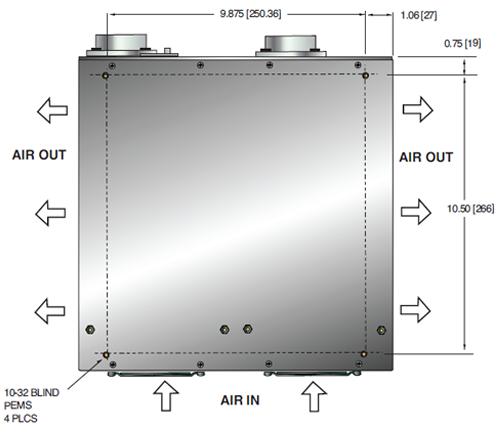
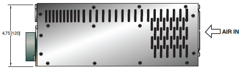
DIMENSIONS: in.[mm]
40-140kV
BOTTOM VIEW
FRONT VIEW
SIDE VIEW
320kV
TOP VIEW
FRONT VIEW
SIDE VIEW
Frequently Asked Questions
Application Notes AN-12 – The Benefit of Using a Current Source to Power X-Ray Tube Filament Circuits
Application Notes AN-01 – Fundamentals of X-Ray Generator – X-Ray Tube Optimization

