XRFシリーズ
- 出力電圧160kV
- ラックマウント可能
- 浮遊フィラメント
- 内部グリッド電源 (80Wモデル)
- 力率改善
- 閉ループ放射制御
- OEMカスタム化可能
*注: すべての仕様は予告なく変更される場合があります。最新版についてはこのデータシートの英語PDFをご覧ください。


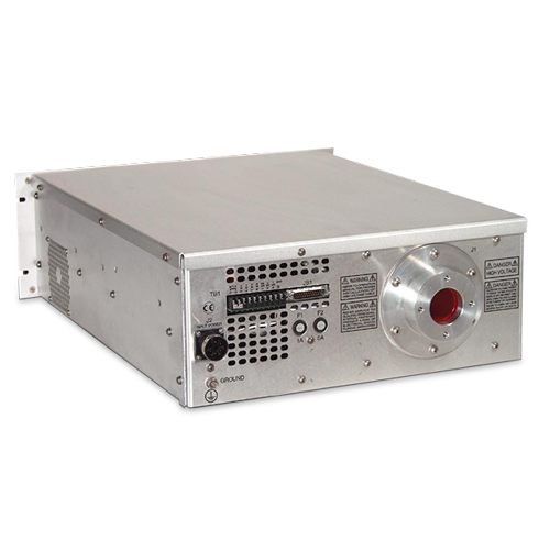
80~640W産業用X線発生器
スペルマンXRFシリーズX線ジェネレータは、広範囲の入力電 圧を可能にし、0〜160kVdc時に80W, 320Wまたは640W の出力を提供します。この軽量でラック・マウント型のX線ジェ ネレータは密閉型、オイル不使用で小型化高圧システムを収容し ています。XRFシリーズは力率改善入力回路を備えた設計で、 広範囲の入力電圧選択を可能にし、他の高周波スイッチング 源 にありがちな放電とノイズを減らします。
XRFシリーズは、エミッション電流の確実なレギュレーション のために、内部フローテング・フィラメントと閉ループ・エミッ ション制御回路を採用しています。電圧/電流/フィラメント電 流のリモート・モニタおよびコントロール機能も付いています。
用途
- X線検査
- 非破壊検査
Specifications
(Ref. 128013-001 REV. R)
Input Voltage:
80W: 90-125Vac at 48-62Hz @ 1.9A
180-264Vac at 48-62Hz @ 0.9A
320W: 180-264Vac at 48-62Hz @ 3.5A
640W: 180-264Vac at 48-62Hz @ 7A
Power Factor:
0.9 or better.
High Voltage Supply:
Output Voltage:
0-160kV, negative polarity.
Output Current:
80W: 0.5mA max. 320W: 2.0mA at 160kV 640W: 4.0mA.
Output Voltage Stability:
Within 0.1% of set value after warm-up period at full load.
Output Voltage Ripple:
80W & 320W: <0.1%, or 160V p-p for high freq. and line freq. at full load.
640W: 0.03% rms <1kHz, 0.75% rms above 1kHz.
Beam Current Stability
80W: Within 0.1% of set value after 1/2 hour warm-up at constant output setting of 30-160kV and line voltage of 90-125 & 180-264Vac.
320W & 640W: Same as 80W except line voltage of 180-264Vac.
Filament Supply: Constant current DC filament supply with closed-loop current feedback.
Filament Voltage: 7V rms (high frequency) max.
Filament Current: 5A max., adjustable 0-5.0A by external Filament Limit Programming input.
Floating Grid Power Supply:
Grid Supply: The grid supply controls tube beam current in a closed-loop regulation design.
Grid Voltage: 0 to 1200Vdc.
Grid Voltage Ripple: Less than 1.0V rms at any frequency.
Grid Supply Response: Less than 0.5mA in less than 10ms.
Control and Monitoring:
Analog Control Inputs: Three inputs have internal load resistance greater than 330kohms.
Voltage Programming:
80W, 320W & 640W:
0 to +10Vdc, where 10.0Vdc = 160kV output.
Beam Tube Current Control:
80W: 0 to +10Vdc, where 10.0Vdc = 0.5mA tube current.
320W: 0 to +10Vdc, where 10.0Vdc = 2.0mA tube current.
640W: 0 to +10Vdc, where 10.0Vdc = 4.0mA tube current.
Filament Current Control:
0 to +10Vdc, where 5.0Vdc = 5.0A filament current.
Analog Monitor Outputs: (See tables for details)
Digital Control Inputs: (See tables for details)
Digital Outputs: (See tables for details)
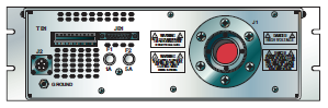
Connections:
Output Connector:
R24 (see owners manual for details)
Input Power Connector:
5-pin male MS-type, Amphenol P/N 97-3102A-18-20P
Control Connector:
25-pin “D” connector, male, chassis-mounted.
Environmental:
0 to +50°C at 10-95% RH, non-condensing.
Forced convection cooling.
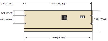
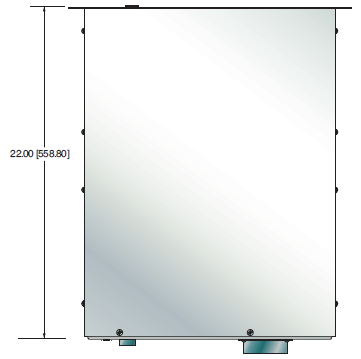
Dimensions:
7”H x 19”W x 22”D (17.8cm x 48.3cm x 55.9cm).
Regulatory Approvals:
Compliant to EEC EMC Directive. Compliant to EEC Low Voltage Directive. RoHS compliant
Options:
DF - Dual Filament AT - Arc Trip
GS - Grid Supply IO - Instant ON
SL - Slides SS(X) - Non Standard Slow Start
Electronic Component (Power Source)
XRF series is intended for installation as a component of a system. It is designed to meet CE standards, with conditions of acceptance often being: customer provided enclosure mounting, EMC filtering, and appropriate protection, and isolation devices. The XRF series is not intended to be operated by end users as a stand-alone device. The XRF series power supply can only be fully assessed when installed within a system, and as a component part within that system.
160kV XRF SELECTION TABLE
| Output Voltage kV | Output Current mA | Output Power W | Model Number XRFxxx |
|---|---|---|---|
| 160 | 0.5 | 80 | XRF160N80 |
| 160 | 2.0 | 320 | XRF160N320 |
| 160 | 4.0 | 640 | XRF160N640 |
J2 AC INPUT CONNECTOR WIRING
| 5 Pin MS Type | 7 Pin UTG Type | Connection |
|---|---|---|
| A | 1 | Auxiliary (Logic) Line |
| B | 2 | Auxiliary (Logic) Neutral |
| C | 3 | Ground |
| D | 4 | Main (Inverter) Line |
| E | 5 | Main (Inverter) Neutral |
JB1 160kV XRF 80W, 320W, 640W 25 PIN
| Pin | Signal | Signal Parameters |
|---|---|---|
| 1 | Filament Limit | 0-5V = 0-5A Filament Limit |
| 2 | High Voltage on Control | +12VDC IN = HV ON |
| 3 | N/C | |
| 4 | N/C | |
| 5 | High Voltage On Status | Low = HV ON |
| 6 | A-Ground | Ground |
| 7 | kV Monitor | 0-10V = 0-160kV |
| 8 | Interlock Control | +12VDC IN = Interlock Closed |
| 9 | N/C | |
| 10 | mA Demand | 0-10V = 0-100% Rated Output |
| 11 | N/C | |
| 12 | N/C | |
| 13 | D-Ground | Ground |
| 14 | Fil. Monitor | 0-5V = 0-5A |
| 15 | N/C | |
| 16 | N/C | |
| 17 | N/C | |
| 18 | N/C | |
| 19 | mA Monitor | 0-10V = 0-100% Rated Output |
| 20 | N/C | |
| 21 | +12VDC Out | |
| 22 | kV Demand | 0-10V = 0-160kV |
| 23 | Grid Inhibit/Fil. Select | Low = Grid Inhibit |
| 24 | N/C | |
| 25 | Chassis Gnd (I/O Shield) | Chassis Gnd. |
160kV XRF 80W, 320W, 640W TERMINAL BLOCK 10 PIN
| Pin | Signal | Signal Parameters |
|---|---|---|
| 1 | Interlock | Jumper to TB1-2 to close interlock |
| 2 | Interlock Return | |
| 3 | kV Monitor | 0-10V=0-160kV |
| 4 | mA Monitor | 0-10V = 0-100% Rated Output |
| 5 | Filament Monitor | 0-5V=0-5A |
| 6 | N/C | |
| 7 | HV ON Indicator | +15V = HV ON |
| 8 | Voltage Mode Indicator | Low = Voltage Mode. |
| 9 | Current Mode Indicator | Low = Current Mode. |
| 10 | GND | Ground |
Tables & Diagrams
DIMENSIONS: in.[mm]
FRONT VIEW
TOP VIEW
BACK VIEW
Frequently Asked Questions
Application Notes AN-12 – The Benefit of Using a Current Source to Power X-Ray Tube Filament Circuits
Application Notes AN-01 – Fundamentals of X-Ray Generator – X-Ray Tube Optimization

