SLM シリーズ
- モデル種類: 1kV~160kV、300W、600W、1200W
- 小型軽量
- ユニバーサル入力、力率改善
- USB、イーサネット、RS-232標準インターフェイス
- CE準拠、UL認証
*注: すべての仕様は予告なく変更される場合があります。最新版についてはこのデータシートの英語PDFをご覧ください。

![]()

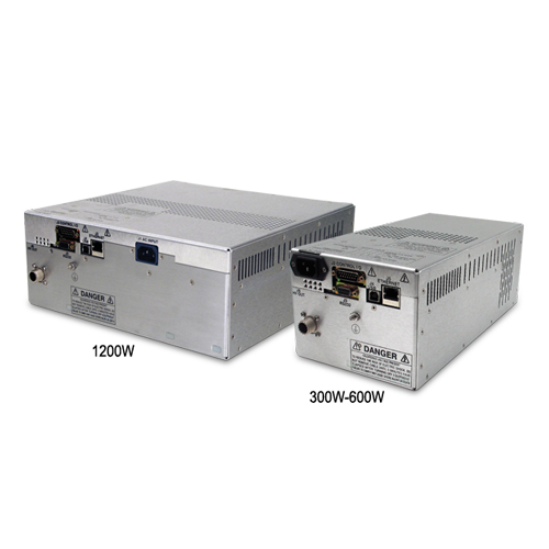
300W~1200W高電圧電源
スペルマンSLMシリーズ高圧モジュールは、OEMアプリケー ション用に設計されており、1200Wで160kV迄対応します。ユ ニバーサル入力、コンパクトなパッケージ・サイズ、さらに3種 類の標準デジタルインターフェースが選択可能で、お客様のシス テム設計に容易に組み込むことが可能です。モデルは正極性そし て負極性が選択可能です。アークおよび短絡保護回路も内 され ています。優れた安定性そしてレギュレーション仕様を提供いた します。
用途
- コンデンサ充電
- ハイポット・テスト
- CRTテスト
- 静電気
- 電子ビーム・システム
- CWレーザ
![]()
Specifications
(Ref. 128035-001 REV. AB)
Input Voltage:
Power factor corrected input ≥0.98
100-240Vac, ±10% (90-264Vac):
47-63Hz @ 4.0A for 300 watt units
200-240Vac, ±10% (180-264Vac):
47-63Hz @ 4.0A for 600 watt units
47-63Hz @ 8.0A for 1200 watt units
Output Voltage:
12 models—1kV to 160kV
Output Polarity:
Negative or positive, specify at time of order
Local Indicators:
Arc, HV On, Temp Error, OVP, I Mode
Power On, OC, Reg Error
Power:
3 power ranges available—300, 600 and 1200 watts. Other power levels available on special order.
Voltage Regulation:
≤ 0.01% of rated output voltage over specified
input voltage range
≤ 0.01% of rated output voltage for a full load change
Current Regulation:
≤ 0.01% of rated output current over specified input voltage range
≤ 0.01% of rated output current for a ±100µA
for a full voltage change
Ripple:
≤ 0.2% rms of maximum rated voltage,
measured with a 10 foot long HV cable
Stability:
≤ 50ppm/hr after a 2 hour warm up
Temperature Coefficient:
≤ 100ppm per degree C
Environmental:
Temperature Range:
Operating: 0°C to 40°C
Storage: -40°C to 85°C
Humidity:
20% to 85% RH, non-condensing.
Control Interface
Local Interface:
Potentiometers are provided to adjust voltage and current.
Remote Interface:
USB, Ethernet and RS-232 are standard, implemented with 12 bits of resolution. All digital monitors have an accuracy specification of 2%.
Control Software:
A Windows graphical user interface
example is provided.
embedded applet for control.
HV Control Enable/Interlock:
A dry contact, hardware based interlock is provided for remote mode. In local mode this I/O is the enable.
Monitor Signals:
Voltage and current monitor signals are scaled 0-10Vdc equals 0-100% of full scale, accuracy is 1%.
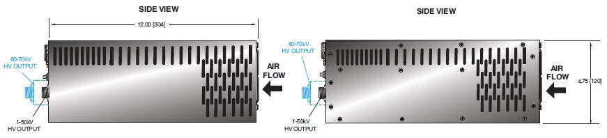
Cooling:
Forced air
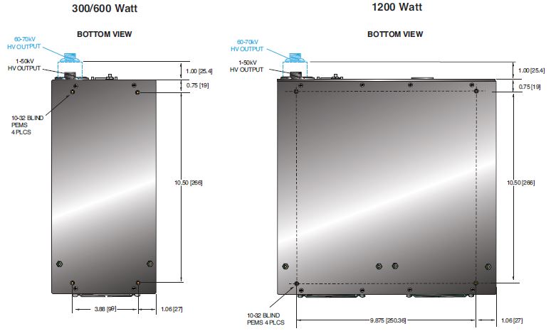
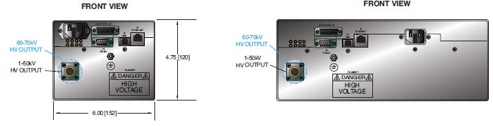
Dimensions:
300/600 watts:
4.75˝ H X 6˝ W X 12˝ D (120.65mm x 152.4mm x 304.8mm)
1200 watts:
4.75˝ H X 12˝ W X 12˝ D (120.65mm x 304.8mm x 304.8mm)
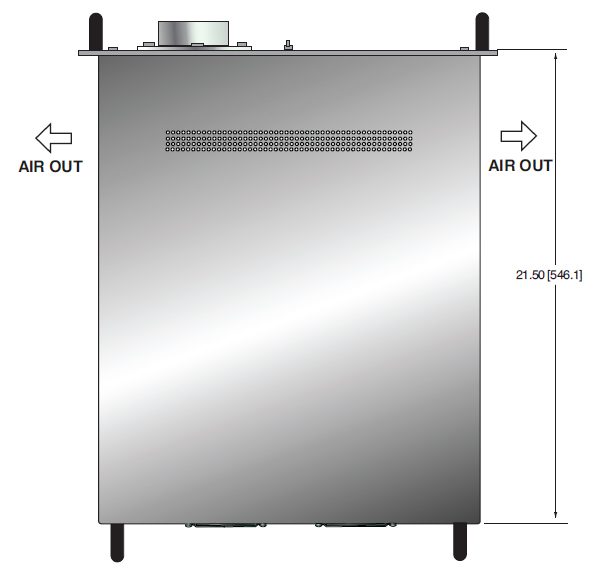
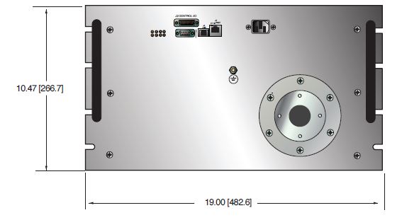
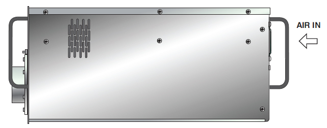
160kV:
10.5˝ H X 19˝ W X 21.5˝ D (266.7mm x 482.6mm x 546.1mm)
Weight:
300/600 watts: 14 pounds (6.35kg)
1200 watts: 26 pounds (11.8kg)
160kV: 142 pounds (64.4kg)
Input Line Connector:
IEC320 cord set with integrated EMI filter
Output Cable:
A detachable 10’ (3.3m) long shielded HV cable is provided.
160kV units: R24 connector. Mating HV cable not provided.
Regulatory Approvals:
Compliant to 204/108/EC, the EMC Directive and 2006/95/EC, the Low Voltage Directive. UL/CUL recognized, File 227588. RoHS compliant. SLM160*1200 is not UL recognized.
FIRMWARE CONFIGURATIONS:
STANDARD BASED FEATURES
AOL - Adjustable Overload Trip
AT - Arc Trip
NAD - No Arc Detect
NSS - No Slow Start
PSS - Programmable Slow Start
RFR - Remote Fault Reset
RMI - Remote Mode Indicators
ROV - Remote Overvoltage Adjust
SLM SELECTION TABLE- 300W
| 300 Watt | ||
|---|---|---|
| kV | mA | Model |
| 1 | 300 | SLM1*300 |
| 3 | 100 | SLM3*300 |
| 5 | 60 | SLM5*300 |
| 10 | 30 | SLM10*300 |
| 15 | 20 | SLM15*300 |
| 20 | 15 | SLM20*300 |
| 30 | 10 | SLM30*300 |
| 40 | 7.5 | SLM40*300 |
| 50 | 6 | SLM50*300 |
| 60 | 5 | SLM60*300 |
| 70 | 4.28 | SLM70*300 |
*Specify “P” for positive polarity or “N” for negative polarity
SLM SELECTION TABLE- 600W
| 600 Watt | ||
|---|---|---|
| kV | mA | Model |
| 1 | 600 | SLM1*600 |
| 3 | 200 | SLM3*600 |
| 5 | 120 | SLM5*600 |
| 10 | 60 | SLM10*600 |
| 15 | 40 | SLM15*600 |
| 20 | 30 | SLM20*600 |
| 30 | 20 | SLM30*600 |
| 40 | 15 | SLM40*600 |
| 50 | 12 | SLM50*600 |
| 60 | 10 | SLM60*600 |
| 70 | 8.56 | SLM70*600 |
*Specify “P” for positive polarity or “N” for negative polarity
SLM SELECTION TABLE- 1200W
| 1200 Watt | ||
|---|---|---|
| kV | mA | Model |
| 1 | 1200 | SLM1*1200 |
| 3 | 400 | SLM3*1200 |
| 5 | 240 | SLM5*1200 |
| 10 | 120 | SLM10*1200 |
| 15 | 80 | SLM15*1200 |
| 20 | 60 | SLM20*1200 |
| 30 | 40 | SLM30*1200 |
| 40 | 30 | SLM40*1200 |
| 50 | 24 | SLM50*1200 |
| 60 | 20 | SLM60*1200 |
| 70 | 17.14 | SLM70*1200 |
| 160 | 7.5 | SLM160*1200 |
*Specify “P” for positive polarity or “N” for negative polarity
SLM ANALOG INTERFACE—J2 15 PIN MALE D CONNECTOR
| Pin | Signal | Signal Parameters |
|---|---|---|
| 1 | Power Supply Fault | Open Collector, 35V @ 10mA Maximum |
| 2 | Current Program In | 0 to 10V=0 to 100% Rated Output, Zin=10MΩ |
| 3 | Voltage Program In | 0 to 10V=0 to 100% Rated Output, Zin=10MΩ |
| 4 | NC | No Connection |
| 5 | Local Voltage Prog. | Multi-turn front panel potentiometer |
| 6 | NC | No Connection |
| 7 | Local Current Prog. | Multi-turn front panel potentiometer |
| 8 | Voltage Monitor | 0 to 10V=0 to 100% Rated Output, Zout =4.99k, 1% |
| 9 | Signal Ground | Ground |
| 10 | Current Monitor | 0 to 10V=0 to 100% Rated Output, Zout =4.99k, 1% |
| 11 | HV Enable Input | Connect to Pin 12 to HV Enable Supply |
| 12 | HV Enable Output | +15V @ Open, ≤15mA @ Closed |
| 13 | NC | No Connection |
| 14 | HV On Output Signal | Open Collector, 35V @10mA Maximum |
| 15 | Spare | No Connection |
RS-232 DIGITAL INTERFACE— J3 9 PIN FEMALE D CONNECTOR
| Pin | Signal | Signal Parameters |
|---|---|---|
| 1 | NC | No Connection |
| 2 | TX out | Transmit Data |
| 3 | RX in | Receive Data |
| 4 | NC | No Connection |
| 5 | SGND | Ground |
| 6 | NC | No Connection |
| 7 | NC | No Connection |
| 8 | NC | No Connection |
| 9 | NC | No Connection |
RS-232 DIGITAL INTERFACE— J4 4 PIN USB "B" CONNECTOR
| Pin | Signal | Signal Parameters |
|---|---|---|
| 1 | VBUS | +5 Vdc |
| 2 | D- | Data - |
| 3 | D+ | Data + |
| 4 | GND | Ground |
ETHERNET DIGITAL INTERFACE— J5 8 PIN RJ45 CONNECTOR
| Pin | Signal | Signal Parameters |
|---|---|---|
| 1 | TX+ | Transmit Data + |
| 2 | TX- | Transmit Data - |
| 3 | RX+ | Receive Data + |
| 4 | NC | No Connection |
| 5 | NC | No Connection |
| 6 | RX- | Receive Data - |
| 7 | NC | No Connection |
| 8 | NC | No Connection |
R24 HV CONNECTOR PINOUT J6 HIGH VOLTAGE OUTPUT (160kV)
| Pin | Output Connection |
|---|---|
| C (common) | High Voltage Output |
| S (small) | High Voltage Output |
| L (large) | High Voltage Output |
Tables & Diagrams
DIMENSIONS: in.[mm]
DIMENSIONS: in.[mm]
160kV
Top View
Front View
Side View
Frequently Asked Questions
What Is a Safe Level of High Voltage?
Where Can I Obtain Information on High Voltage Safety Practices?
What Kind of High Voltage Connector Do You Use on Your Supplies?
What Do You Mean That the Output Side of the High Voltage Cable on Most Standard Products Is “Unterminated”?
How Should I Ground Your Supply?
Why Is Arcing an Issue for a High Voltage Power Supply?
Application Notes AN-18 – Current Loop/Arc Detection Circuitry
Application Notes AN-19 – High Voltage Cable Lengths Discussed

