SERIE SLS
- Salidas de 160 kV-360 kV
- Bajo rizo y alta estabilidad
- Protección contra sobrecorriente, sobrevoltaje y formación de arcos
- Ligera y de tamaño compacto

FUENTES DE ALIMENTACIÓN DE ALTO VOLTAJE DE 2000 W
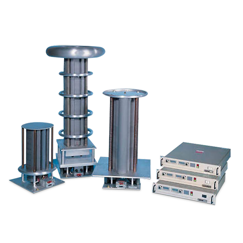
La serie SLS de fuentes de alimentación de alto voltaje proporciona hasta 2000 W de energía con voltajes de salida que van desde los 160 kV a los 360 kV. Estas fuentes de alimentación utilizan inversores resonantes de alta frecuencia con controles de diseño propio para una operación confiable en ambientes extremos. La unidad del multiplicador de alto voltaje está construida con un diseño híbrido de encapsulamiento sólido y aire, reduciendo así su tamaño en general. Compuesta de obleas entrelazadas de 20 kV, la unidad del multiplicador ofrece bloques de construcción flexibles para muchas configuraciones de salida distintas.
Aplicaciones típicas:
- Implantación de iones
- Aceleradores de partículas
- Pistola de electrones
Especificaciones
(Ref. 128016-001 REV. N)
Options
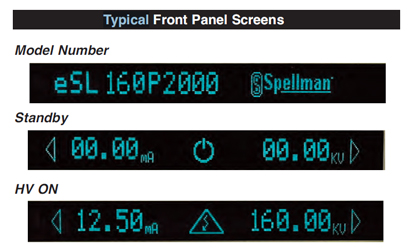
eSL Ethernet Connectivity/VFD Front Panel
Input Voltage:
Standard: 220Vac ±10%, 50/60Hz @ 8A/phase, three phase
Optional: 200Vac ±10%, 50/60Hz @ 8.9A/phase, three phase
Output Voltage Range:
Models available from 160kV to 360kV and up
to 2000W. Each model is available with positive
or negative polarity outputs.
Voltage Regulation:
Better than 0.05% for specified line variations
and load variations.
Ripple:
0.1% p-p of maximum output voltage.
Remote Voltage Control:
0 to +10V for 0 to maximum voltage. Accuracy and
repeatability: 1% of maximum rating.
Remote Current Control:
0 to +10V for 0 to maximum voltage. Accuracy and
repeatability: 1% of maximum rating.
Voltage Monitor:
0 to 10V equivalent to rated voltage. Accuracy, 1% reading.
Current Monitor:
0 to 10V equivalent to rated current. Accuracy, 1% reading.
Stability:
0.05% per hour after 1/2 hour warm-up.
0.05% per 8 hours.
Slow Start:
Slow start times: 6 seconds standard.
Temperature Coefficient:
0.01% per degrees C.
Protection:
Overcurrent, Overvoltage, Arc protection, Overtemperature.
Arc Detect:
If 8 arcs occur in a 10 second, non-synchronous time window, the supply reverts to the Power Down Mode with an ARC fault displayed on the front panel default diagnostic display.
Environmental:
Temperature Range:
Operating: 0°C to 40°C
Storage: -20°C to 85°C
Humidity:
10% to 70%, non-condensing.
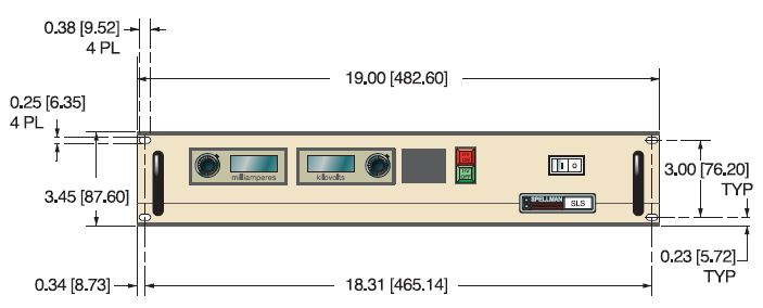
Dimensions:
Inverter Driver Chassis:
3.50”(2U)H x 19.0”W x 19.0”D (8.9cm x 48.3cm x 48.3cm)
Multiplier Unit:
Depends on model specified.
Distance from Stack to Driver:
2.5 meters ±0.1 meter maximum.
Signal Connector:
25 pin, male D connector, J3.
Metering:
Front panel, 3.5 digit, digital voltage and current meters.
Front Panel Controls:
Voltage and current are continuously adjustable by ten-turn potentiometers with lockable counting dials, ON/OFF circuit breaker/lamp, high voltage ON switch/indicator and high voltage OFF switch/indicator.
Front Panel Status Indicators:
Voltage Control Mode Overcurrent
Current Control Mode Overvoltage
Interlock Open Arc
Interlock Closed Regulation Error
High Voltage Inhibit Overtemperature
Overpower (optional)
Regulatory Approvals:
RoHS compliant.
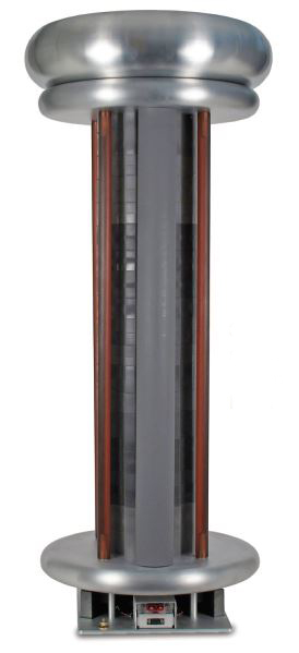
Corona Dome Terminations:
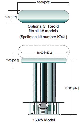
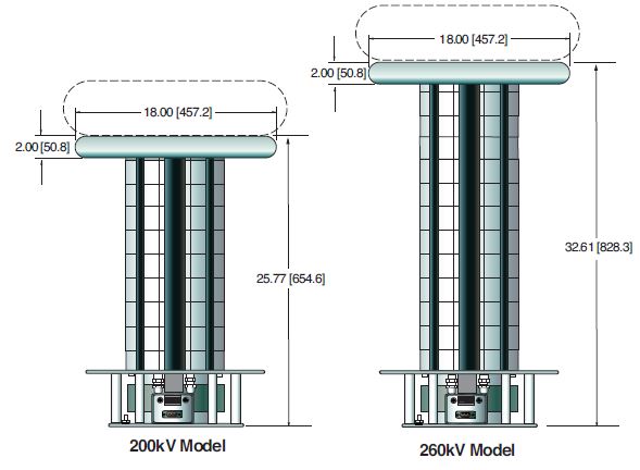
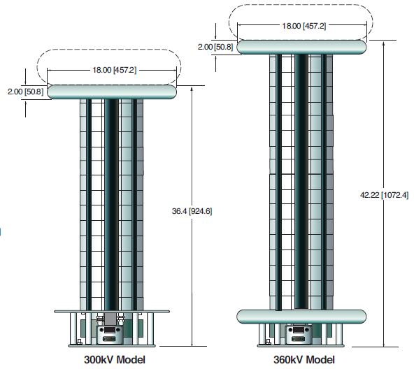
The SLS Series of “stack” configured high voltage power supplies come in a various output voltages and different physical configurations. Appropriate corona relief is required for these units to operate at maximum output voltage. Frequently users will provide the corona relief needed so Spellman will provide stack assemblies that by themselves will not be able to operate at maximum output voltage corona free. Please be certain to discuss your requirements with Spellman to be assured you get a stack assembly in the physical configuration you require for your application. The optional K941 Toroid (5˝ x 20˝) should be considered if customer corona relief will not be provided.
360kV Stack Shown with opptional K941 Toroid
Electronic Component (Power Source)
SLS series is intended for installation as a component of a system. It is designed to meet CE standards, with conditions of acceptance often being: customer provided enclosure mounting, EMC filtering, and appropriate protection, and isolation devices. The SLS series is not intended to be operated by end users as a stand-alone device. The SLS series power supply can only be fully assessed when installed within a system, and as a component part within that system.
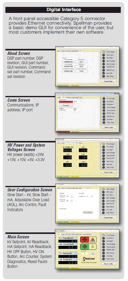
eSL Option
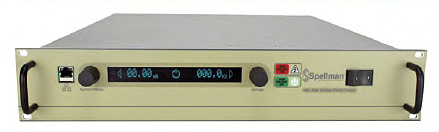
The eSL Option provides a vacuum fluorescent front panel display and Ethernet connectivity. Both the 1U (1.75”) and 2U (3.5”) SL product offerings are available with the eSL Option. Using the front panel local controls the main menu has the following features:
Local/Remote Control
Allows operation from either the local front panel or remotely via the Ethernet Category 5 connector.
Features Menu
Allows control over Adjustable Overload Trip and Slow Start features.
Tutorial Menu
Provides information on how to use the local front panel interface.
Diagnostics Menu
Provides information on the revisions of the hardware, firmware and IP address. Additionally the Diagnostics Menu provides information on the status of the internal low voltage housekeeping power supply voltages.
eSL Option power supplies can still be fully controlled via the SL’s comprehensive remote analog interface, so these units are fully backwards compatible with standard SL power supplies.
SLS SELECTION TABLE
| Maximum Rating | Model Number | |
|---|---|---|
| kV | mA | |
| 160 | 12.5 | SLS160*2000 |
| 200 | 10.0 | SLS200*2000 |
| 260 | 7.7 | SLS260*2000 |
| 300 | 6.6 | SLS300*2000 |
| 360 | 5.5 | SLS360*2000 |
*Specify “P” for positive polarity or “N” for negative polarity Other combinations of voltage and current are available.
SLS I/O INTERFACE CONNECTOR 25 PIN
| Pin | Signal |
|---|---|
| 1 | Power Supply Common |
| 2 | External Inhibit |
| 3 | External Interlock |
| 4 | External Interlock Return |
| 5 | Current Monitor |
| 6 | Voltage Monitor |
| 7 | +10V Reference |
| 8 | Remote Current Program In |
| 9 | Local Current Program Out |
| 10 | Remote Voltage Program In |
| 11 | Local Voltage Program Out |
| 12 | Optional EFR (common) |
| 13 | Optional EFR (normally closed) |
| 14 | Local HV OFF Out |
| 15 | HV OFF |
| 16 | Remote HV ON |
| 17 | Remote HV OFF Indicator |
| 18 | Remote HV ON Indicator |
| 19 | Remote Voltage Mode |
| 20 | Remote Current Mode |
| 21 | Spare |
| 22 | Remote PS Fault |
| 23 | +15V Output |
| 24 | Power Supply Common |
| 25 | Shield Return |
Tablas y Diagramas
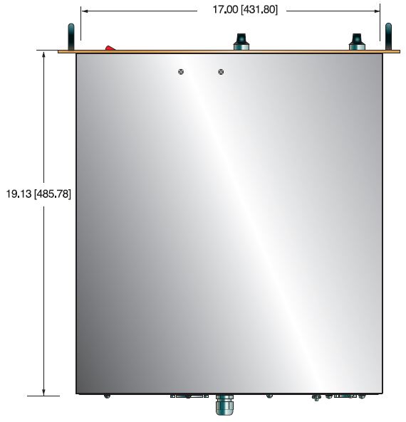
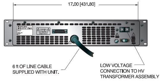
DIMENSIONS: in.[mm]
FRONT VIEW
TOP VIEW
BACK VIEW
Frequently Asked Questions
What Is a Safe Level of High Voltage?
What Is an “External Interlock”?
Where Can I Obtain Information on High Voltage Safety Practices?
What is a Stack Type High Voltage Power Supply?
Why Are Corona Rings/Toroids/Balls Used on High Voltage Power Supplies?
Why Is Arcing an Issue for a High Voltage Power Supply?
Application Notes AN-14 – The Limits of Front Panel Digital Meters
Application Notes AN-15 – 3.5 And 4.5 Digit Meter Displays Explained
Application Notes AN-18 – Current Loop/Arc Detection Circuitry
Application Notes AN-23 – SL HV Off and HV on Circuitry Explained

