SERIE MPS
- Entrada diferencial para programación de voltaje
- Control RS-232/RS-485 opcional
- Monitores y controles de voltaje y corriente
- Alta estabilidad, ruido y rizo ultra bajos
- Marca CE y certificado UL61010A-1
*Nota: Todas las especificaciones están sujetas a cambios sin previo aviso. Consulte la versión en PDF en inglés de esta hoja de datos para obtener la revisión más actualizada.
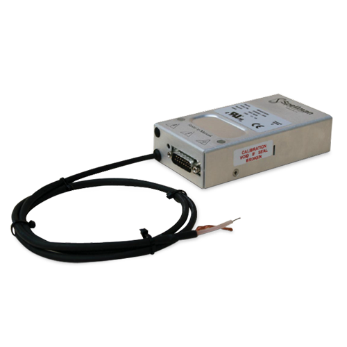
10W DC-DC High Voltage Power Supplies
La nueva serie PMS de Spellman es una familia de módulos de alto voltaje de 10 W que proporciona voltajes de salida que van de 1 kV a 30 kV.
La serie PMS es un conjunto de productos de alto desempeño diseñados con la topología híbrida de Spellman usando técnicas de conversión lineal y de conmutación de energía que suministran una alta eficiencia y bajo ruido. La serie MPS produce especificaciones de excelente desempeño de rizo y estabilidad en un dispositivo compacto. Adicionalmente, la serie MPS cuenta con la función estándar de entrada de amplificador diferencial para la señal de programación de voltaje, lo que proporciona inmunidad contra el ruido externo al sistema y se encarga de cualquier problema de desplazamiento. Alternativamente, la salida de voltaje puede predefinirse mediante un potenciómetro interno.
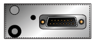
Las interfaces digitales RS-232 o RS-485 también están disponibles como opcionales; tanto los controles analógicos estándar como los digitales opcionales se proporcionan a través de un conector de tipo D de 15 pines.
Las interfaces digitales RS-232 o RS-485 también están disponibles como opcionales; tanto los controles analógicos estándar como los digitales opcionales se proporcionan a través de un conector de tipo D de 15 pines.
Aplicaciones típicas
- Tubos fotomultiplicadores
- Impresión electrostática
- Rayos de electrones e iones
- Escintiladores
- Detectores de multiplicadores de electrones
- Espectrometría de masas
![]()
Especificaciones
(Ref. 128033-001 REV. T)
Input Voltage:
+24 Vdc, ±2Vdc
Input Current:
≤ 1 amp maximum
Output Voltage:
9 models available from 1kV to 30kV
Output Polarity:
Positive or negative, specify at time of order
Power:
10 watts, maximum
Voltage Regulation:
Line: ≤ 0.001% of rated output voltage over specified input voltage
Load: ≤ 0.001% of rated output voltage for full load change
Current Regulation (VCC Option):
Line: ≤ 0.01% for 1V input voltage change under any load conditions
Load: ≤ 0.01% for full load to short circuit
Ripple:
See “model selection” table
Stability:
≤ 0.007% per hour, 0.02% per 8 hours after 1.0 hour warm up period.
≤ 0.05% per 1000 hours after 1.0 hour warm up period (HS option)
Temperature Coefficient:
≤ 25ppm per degree C
≤ 10ppm per degree C (HS option)
Environmental:
Temperature Range:
Operating: 0°C to 50°C
Storage: -35°C to 85°C
Humidity:
20% to 85% RH, non-condensing
Cooling:
Convection cooled
Dimensions:
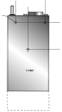
1-10kV: 1.18. H X 2.75. W X 5.12. D (30mm x 70mm x 130mm)
15-20kV: 1.18. H X 2.75. W X 6.49. D (30mm x 70mm x 165mm)
30kV: 1.37. H X 2.95. W X 8.47. D (65mm x 75mm x 215mm)
Weight:
1-3kV: 9.88 oz. (280g)
5-10kV: 14.82 oz. (420g)
15-20kV: 22.92 oz. (650g)
30kV: 35.51 oz. (950g)
Interface Connector:
15 pin male D connector
Output Connectors:
A captive 39.4˝ (1 meter) long shielded HV cable is provided
Regulatory Approvals:
UL recognized component (RC), File E354595. Compliant to EC/UL 61010-1 Safety requirements for electrical equipment for measurement, control and laboratory use; CAN/CSA-C22.2 No.61010-1. CE marked to EN 61010-1. UKAS marked to BS EN 61010-1. RoHS compliant.
As the unit is designed for incorporation within the users system it is not tested against any specific EMC standards. The user will need to take sensible EMC precautions when designing the unit in and verify the overall system EMCperformance against any relevant standards.
Options:
VCC - Variable Current Control
HS - High Stability
DCC 2 - RS-232
DCC 4 - RS-485
Note: It is not possible to supply the unit with both full HS and DCC options
MPS ANALOG INTERFACE— 15 PIN D CONNECTOR (NON-DCC UNITS)
| Pin | Signal | Signal Parameters |
|---|---|---|
| 1 | Power/Signal Ground | Ground (also used as analog signal ground on 1kV to 10kV units) |
| 2 | +24Vdc Input | +24Vdc @ 1 amp maximum |
| 3 | Voltage Monitor Output | 0 to 10Vdc=0 to 100% Rated Output ±2%, Zout =10kΩ |
| 4 | Local Programming Potentiometer Wiper Output | Potentiometer connected to +10Vdc (accuracy: 0.2%) and ground, 0 to 10Vdc adjustable wiper output provided |
| 5 | Voltage Program Input | 0 to 10Vdc=0 to 100% Rated Output ±2%, Zin=10MΩ |
| 6 | Voltage Program Differential Amplifier Output | 0 to 10Vdc=0 to 100% Rated Output, Zout =10kΩ |
| 7 | Voltage Program Differential Amplifier Input—Positive | 0 to 10Vdc differential between pin 7 and pin 9 = 0 to 100% of rated output, diode clamped to ground, Zin =38kΩ |
| 8 | Current Monitor Output | 0 to 10Vdc = 0 to 100% Rated Output ±2%, Zout =10kΩ |
| 9 | Voltage Program Differential Amplifier Input—Negative | 0 to 10Vdc differential between pin 7 and pin 9 = 0 to 100% of Rated Output, diode clamped to ground, Zin =38kΩ |
| 10 | No Connection | No Connection |
| 11 | Current Program Input | Standard: Internally connected to provide 110% fixed current limit VCC Option: 0 to 10Vdc=0 to 100% Rated Output ±2%, Zin=1MΩ |
| 12 | Enable Input | Low = Enable, TTL, CMOS, Open Collector Compliant |
| 13 | Internal Connection | No Connection |
| 14 | Vref (/HS unit only) | +10V ultra high stability reference output. Accuracy: 0.05%, temperature coeff. <5ppm/°C On standard units the reference voltage is available on pin 4 |
| 15 | Analog Signal Ground (15kV to 20kV units) | Analog Signal Ground (No connection for (1kV to 10kV units) |
MPS DIGITAL INTERFACE— 15 PIN D CONNECTOR (DCC UNITS)
| Pin | Signal | Signal Parameters |
|---|---|---|
| 1 | Power/Signal Ground | Ground |
| 2 | +24Vdc Input | +24Vdc @ 1 amp maximum |
| 3 | No Connection | No Connection |
| 4 | Local Programming Potentiometer Wiper Output | Potentiometer connected to +10Vdc and Ground, 0 to 10Vdc adjustable wiper output provided |
| 5 | No Connection | No Connection |
| 6 | No Connection | No Connection |
| 7 | No Connection | No Connection |
| 8 | No Connection | No Connection |
| 9 | No Connection | No Connection |
| 10 | No Connection | No Connection |
| 11 | No Connection | No Connection |
| 12 | Enable Input | Low = Enable, TTL, CMOS, open collector compliant |
| 13 | No Connection | No Connection |
| 14 | TxD | Transmit data (output) with respect to ground (pin 1) |
| 15 | RxD | Receive data (input) with respect to ground (pin 1) |
Notes: 1.) The DCC option operated via a simple ASCII protocol. Contact us for more information.
2.) The HS and DCC option cannot be offered together
MPS SELECTION TABLE
| Model | Output Voltage | Output Current | Ripple (Vpp) |
|---|---|---|---|
| MPS1*10/24 | 1kV | 10mA | <10mV |
| MPS2*10/24 | 2kV | 5.00 mA | <20mV |
| MPS2.5*10/24 | 2.5kV | 4.00 mA | <25mV |
| MPS3*10/24 | 3kV | 3.3mA | <25mV |
| MPS5*10/24 | 5kV | 2mA | <30mV |
| MPS10*10/24 | 10kV | 1mA | <50mV |
| MPS15*10/24 | 15kV | 0.66mA | <100mV |
| MPS20*10/24 | 20kV | 0.5mA | <150mV |
| MPS30*10/24 | 30kV | 0.33mA | <250mV |
*Specify “P” for positive polarity or “N” for negative polarity. Custom units available.
| How To Order: | |||
|---|---|---|---|
| MPSXX*10/24/YYY where: XX is the Output voltage (see selection table) * is the polarity: P for positive / N for negative YYY is the option: VCC / HS / DCC2 / DCC4 |
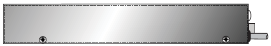
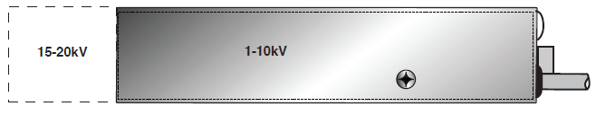
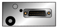
Tablas y Diagramas
DIMENSIONS: in.[mm]
1-20kV
FRONT VIEW
BOTTOM VIEW
SIDE VIEW
30kV
FRONT VIEW
BOTTOM VIEW
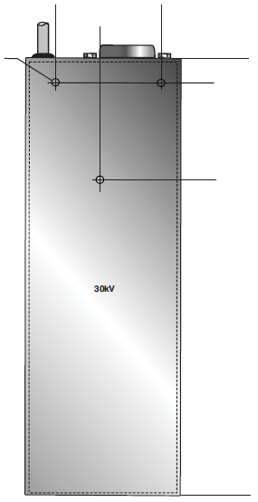
SIDE VIEW