")
XRB100N100 Monoblock® Industrial X-Ray Generators
- Integrated HV Supply, Filament Supply, X-Ray Tube, Beam Port and Control Electronics
- Compact & Lightweight
- Universal input, Power Factor Corrected with Internal EMI Filter
- Can be Mounted in Any Physical Orientation
- Analog Control Interface and Standard RS-232 Digital Interface
*Note: All specifications are subject to change without notice. Please consult the English PDF version of this datasheet for the most up-to-date revision.
100kV, 100W X-Ray Source
Spellman’s XRB100N100 Monoblock® X-Ray source is designed for OEM applications powering its internal X-Ray tube up to 100kV at 100W. Features like universal input, small package size and a standard analog and RS-232 digital interface simplify integrating this Monoblock® into your X-Ray system. Proprietary emission control circuitry provides excellent regulation of X-Ray tube current, along with outstanding stability performance.
Typical applications:
- X-Ray Scanning: Food Inspection
- Fill Level Confirmation
- Security Applications
Specifications
(Ref. 128072-001 REV. L)
X-Ray Characteristics:
Tube Type: Stationary anode, tungsten target
Focal Spot: 0.5mm (IEC 336)
Beam Filter: Lexan: 3.2mm
Oil: 10mm ±0.1mm
Glass: 1.8mm max
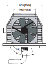
Beam Geometry: Symmetrical fan 74° x 10° ±1°
Input Voltage:
Power factor corrected input 0.98, 100-240Vac ±10% 50/60Hz, 2A, maximum
X-Ray Tube Voltage:
Nominal X-Ray tube voltage is adjustable between 40kV to 100kV
X-Ray Tube Current:
100uA to 1mA over specified tube voltage range
X-Ray Tube Power:
100W, maximum continuous
Voltage Regulation:
Line: ±0.1% of maximum output voltage over a ±10% change of nominal input line voltage
Load: ±0.1% of maximum rated voltage for 100uA to 1mA load change
Voltage Accuracy:
Voltage measured across the X-Ray tube is within ±2% of the programmed value
Voltage Risetime:
Ramp time shall be 1 second from 10% to 90% of maximum rated output voltage
Voltage Overshoot:
5% of maximum voltage, to return within 2.5% of maximum voltage in less than 50ms
Voltage Ripple:
0.5% peak to peak of maximum voltage for frequencies ≤ 1kHz
Emission Current Parameters Current Regulation:
Line: ±0.5% of rated output current over a ±10% change of nominal input line voltage
Load: ±0.5% of rated output current for a change from 50% to 100% of rated output voltage
Current Accuracy:
Current measured through the X-Ray tube is within ±1% of the programmed value
Current Risetime:
Ramp time shall be 1 second from 10% to 90% of maximum rated current
Arc Intervention:
3 arcs in 10 seconds with a 200ms quench = Shutdown
Filament Configuration:
Internal high frequency AC filament drive with closed loop filament emission control
Analog Interface:
Ground referenced 0 to 9Vdc for all programming and monitoring signals. Relay contacts and open collector signals for other signals. See analog interface connector pin out table.
Digital Interface:
Jumpers are needed to be configured and the digital interface cable installed to enable the RS-232 interface.
Control Software:
A demo GUI is available for engineering evaluations.
Interlock/Signals:
A hardware interlock functions in both analog and digital programming modes. The hardware X-Ray Enable signal only functions in analog programming mode.
Operating Temperature:
0°C to +40°C
Storage Temperature:
-40°C to +70°C
Humidity:
10% to 95% relative humidity, non-condensing
Cooling:
Forced air and natural convection augmented by customer provided external cooling fan to maintain oil temperature below 55°C.
Input Line Connector:
3 pin, Phoenix Contact 1829167, SHV part number 105725-219. Mating connector Phoenix Contact #1805990, SHV part number 105808-475 provided with unit.
Analog Interface Connector:
15 pin D connector, male
Digital Interface Connector:
9 pin D connector, female
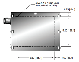
Grounding Point:
M4 ground stud provided on chassis
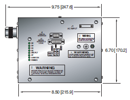
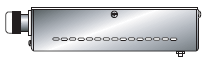
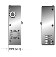
Dimensions:
See page 3 of 3
Weight:
55lbs (25kg)
Orientation:
Can be mounted in any orientation.
X-Ray Leakage:
Not to be greater than 0.5mR/hr at 5cm outside the external surface.
AC LINE POWER CONNECTOR— J1 THREE POSITION PHOENIX CONTACT
| Pin | Signal |
|---|---|
| 1 | Earth Ground |
| 2 | Line |
| 3 | Neutral |
Mating connector provided with unit
RS-232 DIGITAL INTERFACE— J3 9 PIN FEMALE D CONNECTOR
| Pin | Signal | Parameters |
|---|---|---|
| 1 | N/C | No Connection |
| 2 | TD | Transmit Data |
| 3 | RD | Receive Data |
| 4 | N/C | No Connection |
| 5 | SGND | Signal Ground |
| 6 | NC | No Connection |
| 7 | NC | No Connection |
| 8 | NC | No Connection |
| 9 | NC | No Connection |
XRB ANALOGINTERFACE— J2 15 PIN MALE D CONNECTOR
| Pin | Signal | Parameters |
|---|---|---|
| 1 | Power Supply Fault Output PARAMETERS |
Open collector, 35V @ 10mA max. high = no fault |
| 2 | mA Program Input | 0 to 9.00Vdc = 0 to 100% rated output, Zin =10MΩ |
| 3 | kV Program Input | 0 to 9.00Vdc = 0 to 100% rated output, Zin =10MΩ |
| 4 | X-Ray On Lamp Relay Output | Common, dry contacts, 30Vdc @ 1A, max |
| 5 | X-Ray On Lamp Relay Output | Normally open, X-Ray ON = closed |
| 6 | mA Monitor Output | 0 to 9Vdc = 0 to 100% rated output, Zout =10kΩ |
| 7 | X-Ray On Lamp Relay Output | Normally closed, X-Ray ON = open |
| 8 | kV Monitor Output | 0 to 9.00Vdc = 0 to 100% rated output, Zout =10kΩ |
| 9 | Signal Ground | Ground |
| 10 | Signal Ground | Ground |
| 11 | HV Interlock Return Input | Connect to Pin 12 to close HV interlock |
| 12 | HV Interlock Output | +15Vdc @ open, 5mA when connected to pin 11 |
| 13 | X-Ray Enable Output | +15Vdc @ open, 5mA when connected to pin 15 |
| 14 | X-Ray Status Output | Open collector, 35V @ 10mA max high = X-Ray OFF |
| 15 | X-Ray Enable Return Input | Connect to pin 13 to enable X-Ray generation |
XRB ANALOGINTERFACE— J2 15 PIN MALE D CONNECTOR
| Indicator | Signal Name | Condition Illuminated When... |
|---|---|---|
| LED 1 | OV | High kV occurs |
| LED 2 | UV | Low kV occurs |
| LED 3 | UC | Low mA occurs |
| LED 4 | OC | High mA occurs |
| LED 5 | ARC FLT | Arc fault occurs |
| LED 6 | OT | Over temperature occurs |
| LED 7 | X-RAY ON | X-Rays are enabled |
| LED 8 | PWR | Power is ON |
Tables & Diagrams
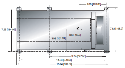
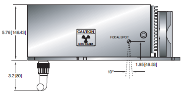
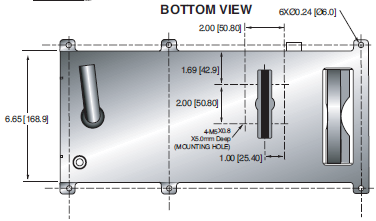
DIMENSIONS: in.[mm]
X-RAY GENERATOR
FRONT VIEW
TOP VIEW
SIDE VIEW
BOTTOM VIEW
CONTROL UNIT
FRONT VIEW
TOP VIEW
SIDE VIEW
BOTTOM VIEW
Frequently Asked Questions
Why Is Oil Insulation Used?
Do I Need to Ensure My Monoblock® Stays Cool? Why?
How Often Do I Need to Season My Monoblock® X-Ray Source? Why?
Application Notes AN-12 – The Benefit of Using a Current Source to Power X-Ray Tube Filament Circuits

