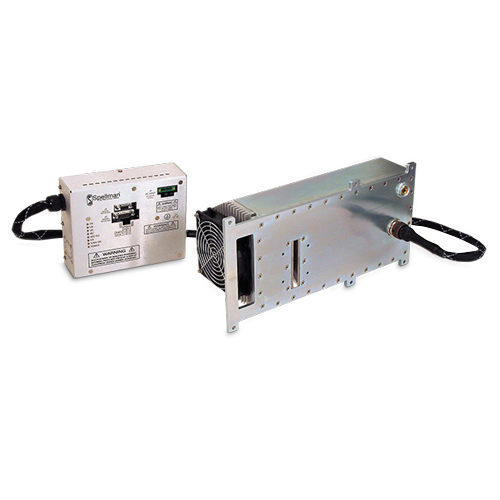
SERIE XRB100N100
- Fuente de alto voltaje con alimentación de filamento, tubo de rayos X, puerto de haz y electrónica de control integrados
- Compacta y ligera
- Entrada universal, factor de potencia corregido con filtro interno de EMI
- Se puede montar en cualquier orientación física
- Interfaz de control analógica e interfaz de control digital estándar RS-232
FUENTE DE RAYOS X DE 100 KV, 100 W
El generador de rayos X XRB100N100 monoblock® de Spellman está diseñado para aplicaciones OEM que alimentan su tubo de rayos X interno de hasta 100 kV a 100W. Características como la entrada universal, el tamaño pequeño, una interfaz analógica y RS-232 digital estándar simplifican la integración de este Monoblock® en su sistema de rayos X. Los circuitos patentados de control de emisiones proporcionan una excelente regulación de la corriente del tubo de rayos X, junto con un rendimiento de estabilidad excepcional.
Aplicaciones típicas:
- Barrido con rayos X: inspección de alimentos
- Confirmación de nivel de llenado
- Aplicaciones de seguridad
Especificaciones
(Ref. 128072-001 REV. L)
X-Ray Characteristics:
Tube Type: Stationary anode, tungsten target
Focal Spot: 0.5mm (IEC 336)
Beam Filter: Lexan: 3.2mm
Oil: 10mm ±0.1mm
Glass: 1.8mm max
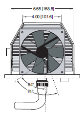
Beam Geometry: Symmetrical fan 74° x 10° ±1°
Input Voltage:
Power factor corrected input 0.98, 100-240Vac ±10% 50/60Hz, 2A, maximum
X-Ray Tube Voltage:
Nominal X-Ray tube voltage is adjustable between 40kV to 100kV
X-Ray Tube Current:
100uA to 1mA over specified tube voltage range
X-Ray Tube Power:
100W, maximum continuous
Voltage Regulation:
Line: ±0.1% of maximum output voltage over a ±10% change of nominal input line voltage
Load: ±0.1% of maximum rated voltage for 100uA to 1mA load change
Voltage Accuracy:
Voltage measured across the X-Ray tube is within ±2% of the programmed value
Voltage Risetime:
Ramp time shall be 1 second from 10% to 90% of maximum rated output voltage
Voltage Overshoot:
5% of maximum voltage, to return within 2.5% of maximum voltage in less than 50ms
Voltage Ripple:
0.5% peak to peak of maximum voltage for frequencies ≤ 1kHz
Emission Current Parameters Current Regulation:
Line: ±0.5% of rated output current over a ±10% change of nominal input line voltage
Load: ±0.5% of rated output current for a change from 50% to 100% of rated output voltage
Current Accuracy:
Current measured through the X-Ray tube is within ±1% of the programmed value
Current Risetime:
Ramp time shall be 1 second from 10% to 90% of maximum rated current
Arc Intervention:
3 arcs in 10 seconds with a 200ms quench = Shutdown
Filament Configuration:
Internal high frequency AC filament drive with closed loop filament emission control
Analog Interface:
Ground referenced 0 to 9Vdc for all programming and monitoring signals. Relay contacts and open collector signals for other signals. See analog interface connector pin out table.
Digital Interface:
Jumpers are needed to be configured and the digital interface cable installed to enable the RS-232 interface.
Control Software:
A demo GUI is available for engineering evaluations.
Interlock/Signals:
A hardware interlock functions in both analog and digital programming modes. The hardware X-Ray Enable signal only functions in analog programming mode.
Operating Temperature:
0°C to +40°C
Storage Temperature:
-40°C to +70°C
Humidity:
10% to 95% relative humidity, non-condensing
Cooling:
Forced air and natural convection augmented by customer provided external cooling fan to maintain oil temperature below 55°C.
Input Line Connector:
3 pin, Phoenix Contact 1829167, SHV part number 105725-219. Mating connector Phoenix Contact #1805990, SHV part number 105808-475 provided with unit.
Analog Interface Connector:
15 pin D connector, male
Digital Interface Connector:
9 pin D connector, female
Grounding Point:
M4 ground stud provided on chassis
Dimensions:
See page 3 of 3
Weight:
55lbs (25kg)
Orientation:
Can be mounted in any orientation.
X-Ray Leakage:
Not to be greater than 0.5mR/hr at 5cm outside the external surface.
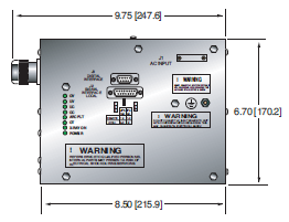
AC LINE POWER CONNECTOR— J1 THREE POSITION PHOENIX CONTACT
| Pin | Signal |
|---|---|
| 1 | Earth Ground |
| 2 | Line |
| 3 | Neutral |
Mating connector provided with unit
RS-232 DIGITAL INTERFACE— J3 9 PIN FEMALE D CONNECTOR
| Pin | Signal | Parameters |
|---|---|---|
| 1 | N/C | No Connection |
| 2 | TD | Transmit Data |
| 3 | RD | Receive Data |
| 4 | N/C | No Connection |
| 5 | SGND | Signal Ground |
| 6 | NC | No Connection |
| 7 | NC | No Connection |
| 8 | NC | No Connection |
| 9 | NC | No Connection |
XRB ANALOGINTERFACE— J2 15 PIN MALE D CONNECTOR
| Pin | Signal | Parameters |
|---|---|---|
| 1 | Power Supply Fault Output PARAMETERS |
Open collector, 35V @ 10mA max. high = no fault |
| 2 | mA Program Input | 0 to 9.00Vdc = 0 to 100% rated output, Zin =10MΩ |
| 3 | kV Program Input | 0 to 9.00Vdc = 0 to 100% rated output, Zin =10MΩ |
| 4 | X-Ray On Lamp Relay Output | Common, dry contacts, 30Vdc @ 1A, max |
| 5 | X-Ray On Lamp Relay Output | Normally open, X-Ray ON = closed |
| 6 | mA Monitor Output | 0 to 9Vdc = 0 to 100% rated output, Zout =10kΩ |
| 7 | X-Ray On Lamp Relay Output | Normally closed, X-Ray ON = open |
| 8 | kV Monitor Output | 0 to 9.00Vdc = 0 to 100% rated output, Zout =10kΩ |
| 9 | Signal Ground | Ground |
| 10 | Signal Ground | Ground |
| 11 | HV Interlock Return Input | Connect to Pin 12 to close HV interlock |
| 12 | HV Interlock Output | +15Vdc @ open, 5mA when connected to pin 11 |
| 13 | X-Ray Enable Output | +15Vdc @ open, 5mA when connected to pin 15 |
| 14 | X-Ray Status Output | Open collector, 35V @ 10mA max high = X-Ray OFF |
| 15 | X-Ray Enable Return Input | Connect to pin 13 to enable X-Ray generation |
XRB ANALOGINTERFACE— J2 15 PIN MALE D CONNECTOR
| Indicator | Signal Name | Condition Illuminated When... |
|---|---|---|
| LED 1 | OV | High kV occurs |
| LED 2 | UV | Low kV occurs |
| LED 3 | UC | Low mA occurs |
| LED 4 | OC | High mA occurs |
| LED 5 | ARC FLT | Arc fault occurs |
| LED 6 | OT | Over temperature occurs |
| LED 7 | X-RAY ON | X-Rays are enabled |
| LED 8 | PWR | Power is ON |
Tablas y Diagramas
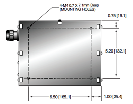
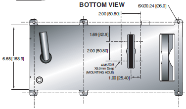
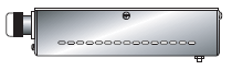
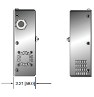
DIMENSIONS: in.[mm]
X-RAY GENERATOR
FRONT VIEW
TOP VIEW
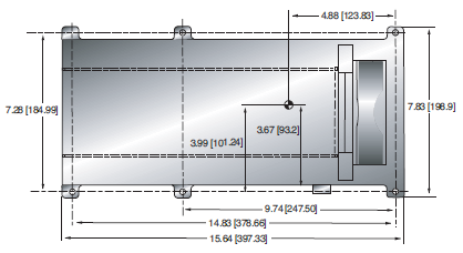
SIDE VIEW
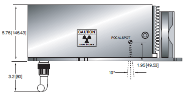
BOTTOM VIEW
CONTROL UNIT
FRONT VIEW
TOP VIEW
SIDE VIEW
BOTTOM VIEW