EBM20N5/24
- Triode Supply for Electron Beam Columns
- High Precision, Low Noise, Ultra Stable
- Over Current/Voltage Protection
- Arc and Short Circuit Protection
- OEM Customization Available
- UL Certified, CE Marked and RoHS Compliant
*Note: All specifications are subject to change without notice. Please consult the English PDF version of this datasheet for the most up-to-date revision.


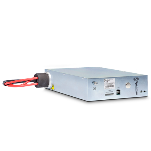
OEM Module for SEM Applications
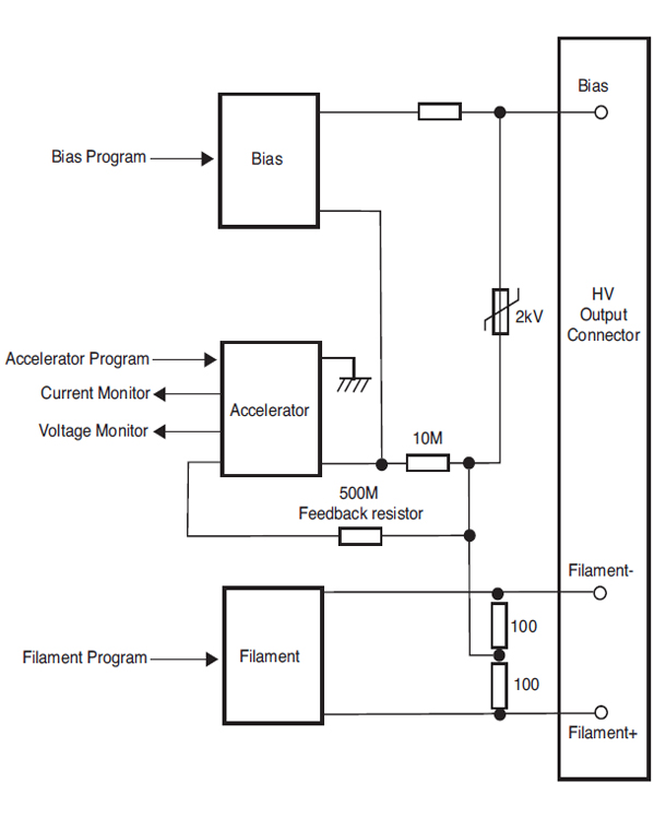
The EBM20N5/24 powers E-Beam Columns in Thermionic Scanning Electron Microscopes providing acceleration, bias and filament sources in a single compact package. Spellman’s proprietary HV packaging and encapsulation technology gives dramatic improvements in size, cost and performance compared to other SEM power supply offerings. The EBM20N5/24 provides a highly regulated, low noise, ultra stable accelerator supply programmable from 0 to -20kV at 250uA. The EBM20 has floating bias and filament supplies referenced to the accelerator. Programming signals utilize differential analog inputs to minimize external noise and offset voltages effects. A ground referenced accelerator current monitor is provided. The EBM20 is arc and short circuit immune, along with over voltage and over current protection.
Typical applications:
- Scanning Electron Microscope
Specifications
(Ref. 128031-001 REV. D)
SPECIFICATIONS:
Input Voltage:
+24Vdc, ±5%, 1.5A maximum
High Voltage Outputs:
ACCELERATOR:
Voltage:
0V to -20kV full load with respect to ground
Current:
250μA maximum (including feedback current), continuous
from -500V to -20kV.
Current Trip Level:
275mA, ±10%. Trips off all outputs, reset by cycling
i nput power
Accuracy (voltage program):
±1% from -500V to -20kV
Load Regulation:
<±100ppm, 20μA to 250μA load change
Line Regulation:
<±100ppm for 10% line change
Ripple:
<20ppm p-p at -20kV, 250μA, maximum bias and filament output
Temperature Coefficient:
<100ppm/°C
Stability:
30ppm/3 minutes at 100μA load current after 1 hour warm up
Rise Time (switch ON):
<3 seconds (0% to 90%) with no overshoot
Fall Time (switch OFF):
<100 seconds (to <50 volts)
BIAS:
(Referenced to Accelerator)
Voltage:
0 to +1.5kV (max allowable output limited to 2kV)
Current:
150µA maximum
Accuracy (voltage program):
±3% of full scale
Line Regulation:
<±0.1% for 10% line change
Ripple:
<0.1% p-p
Temperature Coefficient:
<1000ppm/°C
Stability:
1%/10 minutes
Rise Time (switch ON):
<3 seconds (0% to 90%) with no overshoot
Fall Time (switch OFF):
<100 seconds (to <50 volts)
FILAMENT:
(center voltage WRT accelerator output)
Power:
0 to 12W
Load Resistance:
1.33Ω ±5%
Accuracy:
±3% of FS
Load Regulation:
<1% for 10% change in load resistance
Line Regulation:
<1% for 10% line voltage change
Ripple:
<0.1% p-p max
Temperature Coefficient:
<300ppm/°C
Stability:
100ppm/10 minutes
INTERFACE:
Input:
Analog control for accelerator, filament and bias
High Voltage Output:
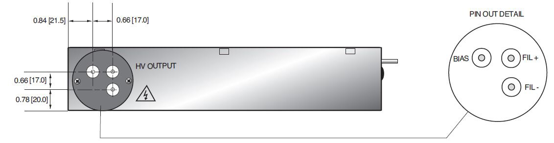
Custom 3 pin receptacle and cable assembly
Temperature:
Operating: 5°C to +40°C
Storage: -20°C to +50°C
Humidity:
20% to 85% RH, non-condensing
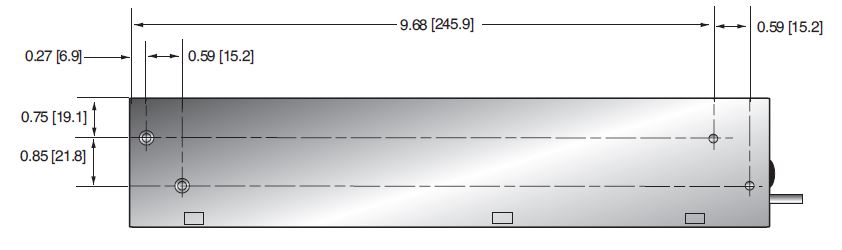
Dimensions:
10.63˝H x 2.36˝W x 7.87˝D (270mm x 60mm x 200mm) excluding any mounting brackets
Weight:
<10 lbs. (4.5kg)
Regulatory Approvals:
UL recognized component (RC). File number E354595. Compliant to IEC/UL 61010-1 Safety requirements for electrical equipment for measurement, control and laboratory use; CAN/CSA-C22.2 No.61010-1. CE marked to EN 61010-1. UKCA marked to BS EN 61010-1. RoHS compliant. As the unit is designed for incorporation within the users system it is not tested against any specific EMC standards. The user will need to take sensible EMC precautions when designing the unit in and verify the overall system EMC performance against any relevant standards.
POWER INPUT CONNECTOR JHA2 3 PIN JST MODEL B 3PS-VH
| Pin | Signal | Parameters |
|---|---|---|
| 1 | +24V High Voltage Power Input | +24Vdc Input |
| 2 | 0V Input | +24Vdc Common |
| 3 | FG | Chassis Ground |
CONTROL AND MONITORING CONNECTOR JHA3 10 PIN JST MODEL S10B-EH
| Pin | Signal | Parameters |
|---|---|---|
| 1 | FIL PROG (+) | Filament Program (+) Input |
| 2 | GND | Ground |
| 3 | BIAS (+) | Bias (+) Input |
| 4 | GND | Ground |
| 5 | ACC PROG (+) | Acc Voltage Program (+) Input |
| 6 | GND | Ground |
| 7 | EMS | Emission Current Monitor Output |
| 8 | GND | Ground |
| 9 | ACC MON | ACC Voltage Monitor Output |
| 10 | GND | Ground |
| How to order: | ||
|---|---|---|
| Standard: PART NO.:EBM20N5/24 | ||
| HV Cable: PART NO.:HVC30/3IS/LL1650 (1.65m Cable) |
Tables & Diagrams
HV CABLE ASSEMBLY DETAILS
DIMENSIONS: in.[mm]
SIDE VIEW
TOP VIEW
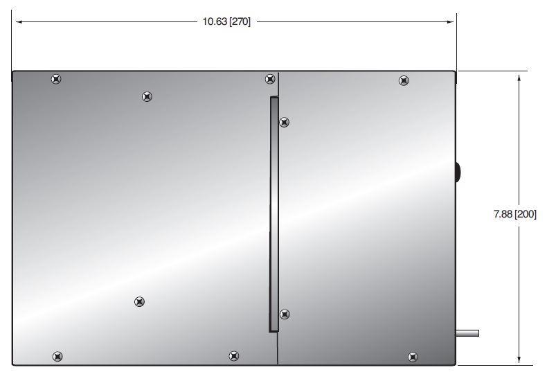
FRONT VIEW
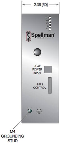
SIDE VIEW