")
CCM1KW Series
- Compact & Lightweight Package
- Factor Corrected Input
- Cost Modular OEM Platform
- Resonant Soft Switching Inverter Topology
- UL/CUL Recognized; RoHS Compliant
*Note: All specifications are subject to change without notice. Please consult the English PDF version of this datasheet for the most up-to-date revision.


1kW Capacitor Charging Module
Spellman’s CCM1KW capacitor charging module is designed to provide up to 1000 Joules per second at an output voltage up to 4000 Volts. The power factor corrected AC input, small package size and both a comprehensive and minimal analog interface simplifies integrating the CCM1KW into your OEM system design. Available in either positive or negative polarity, the CCM1KW is fully arc, open and short circuit protected. Units can be operated in parallel for applications requiring higher power (see manual for details).
Typical applications:
- UV light sources for curing and sterilization Industrial and medical laser applications
Specifications
(Ref. 128103-001 REV. K)
Input Voltage:
90-264 Vac, 50/60 Hertz, power factor corrected input ≥0.98
Input Current:
14 Amps worst case, 1000 Joules per second
7 Amps worst case, 500 Joules per second
Efficiency:
>85%
Output Power:
1000 Joules per second, 500 Joules per second
Output Voltage:
0-1kV, 0-2kV and 0-4kV version available
Output Polarity:
Positive or negative, specify at time of order
Stored Energy:
Less than 0.2 Joules
Pulse to Pulse Repeatability:
±0.2% up to 1kHz
Temperature Coefficient:
≤ 100ppm per degree C
Fault Diagnostic System:
Over Temperature and Over Voltage Over Voltage Fault is latched requiring AC power recycle to clear. Over Temperature Fault is latched but can be cleared via inhibit/fault reset line.
Environmental:
Temperature Range:
Operating: 0°C to 40°C
Storage: -40°C to 85°C
Humidity:
10% to 90% RH, non-condensing
Cooling:
Forced air
Input Line Connector:
2 position Phoenix MSTB connector, straight and right angle mating connector provided
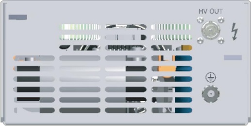
HV Output Connector:
Standard: Kings/Winchester Electronics SHV 1707-1
Optional: Amphenol MHV UG-931/U
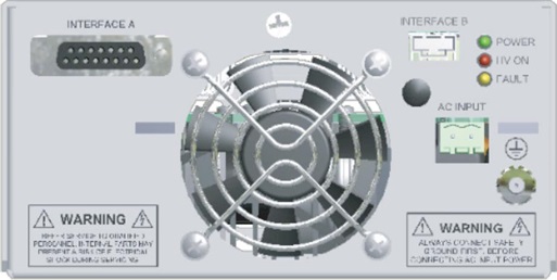
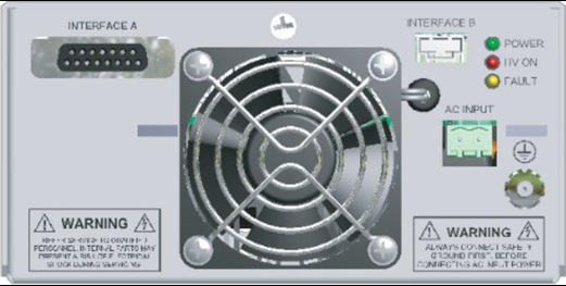
Interface-A Connector:
15 pin D, female
Interface-B Connector:
4 pin male Molex 705530038
Ground Stud:
10-32, nut supplied
Dimensions:
3. H X 6. W X 9. D (76.2mm x 152.4mm x 228.6mm)
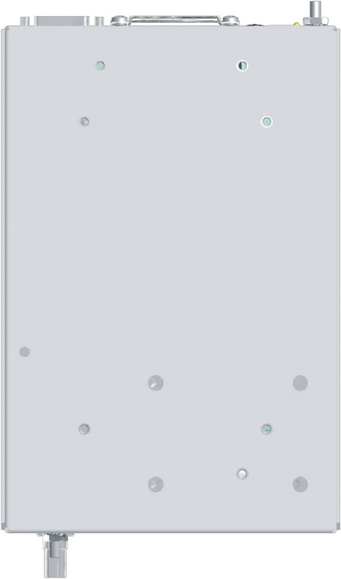
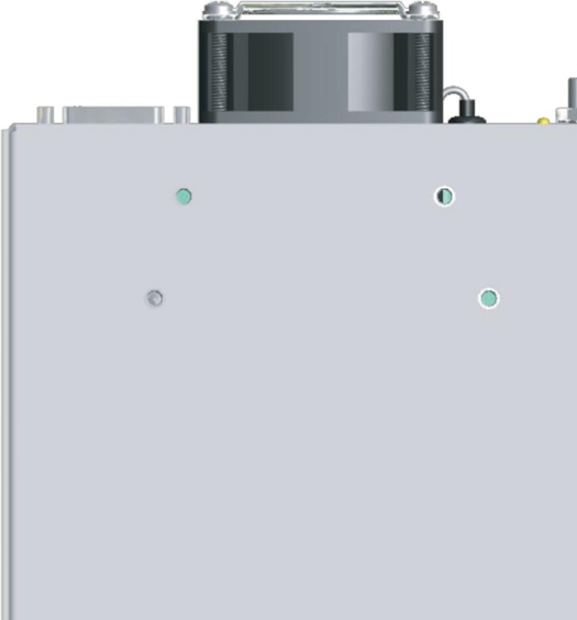
Mounting:
M4 screw. Max. depth is 0.188. (4.78mm)
Weight:
6.9lb. (3.13kgs)
Regulatory Approvals:
Compliant to 60601-1-1. Compliant to 60601-1-2. UL/CUL recognized file E242584. RoHS compliant.
AC INPUT–2 POSITION TERMINAL BLOCK
| Pin | Signal | Signal Parameters |
|---|---|---|
| 1 | AC Input High/Phase 1 | Line Hot/Phase 1 |
| 2 | AC Input Low/Phase 2 | Line Neutral/Phase 2 |
ANALOG INTERFACE A— 15 PIN FEMALE D CONNECTOR
| Pin | Signal | Signal Parameters |
|---|---|---|
| 1 | Inhibit/Fault Reset | Ground = HV Enable, Open/+15Vdc = HV Inhibit |
| 2 | N/C | N/C |
| 3 | OverTemp Fault | No OT Fault = +15Vdc @ 3mA, OT Fault = Ground |
| 4 | Signal Ground | Signal Ground (optional)* |
| 5 | Voltage Program | 0 to 10Vdc = 0 to 100% rated output voltage |
| 6 | Overvoltage Status | No OVP = +15Vdc @ 3mA, OVP Fault = Ground |
| 7 | Peak Hold Monitor | Peak output voltage displayed, 0 to 10Vdc = 0 to 100% rated output voltage with a 5 second time constant |
| 8 | Voltage Monitor | 0 to 10Vdc = 0 to 100% rated output voltage, ±1% |
| 9 | +15Vdc | +15Vdc @ 150mA, maximum** |
| 10 | N/C | N/C |
| 11 | +15Vdc | +15Vdc @ 150mA, maximum (optional)** |
| 12 | Signal Ground | Signal Ground (optional)* |
| 13 | End of Charge | Charging = +15Vdc @ 1.5mA, End of Charge = Ground |
| 14 | Signal Ground | Signal Ground |
| 15 | Signal Ground | Signal Ground |
Note: Output status signals are NMOS transistor controlled, 100mA maximum sink current. Actual signals are 5kΩpull ups to the internal +15Vdc logic source.
*Optional interface signals can be provided to be compatable with other pre-existing legacy interfaces. On standard units these signals are N/C.
**+15Vdc ±10% is provided on the standard unit. Optional +12Vdc ±5%/100mA, maximum can be provided.
INTERFACE B–4 PIN MALE D HEADER
| Pin | Signal | Signal Parameters |
|---|---|---|
| 1 | Inhibit/Fault Reset | Ground = HV Enable, Open/+15Vdc = HV Inhibit |
| 2 | Signal Ground | Signal Ground |
| 3 | Voltage Program | 0 to 10Vdc = 0 to 100% rated output voltage |
| 4 | +15Vdc | +15Vdc @ 150mA, maximum (optional)* |
CCM1KW SELECTION TABLE kV JOULES/SECOND
| kV | Joules/Second | |
|---|---|---|
| 1 | 500 | CCM1*500 |
| 2 | 500 | CCM2*500 |
| 4 | 500 | CCM4*500 |
| 1 | 1000 | CCM1*1000 |
| 2 | 1000 | CCM2*1000 |
| 4 | 1000 | CCM4*1000 |
*Specify P for positive or N for negative 500 J/s units have a single internal fan, 1000 J/s units have both an internal and external fan.
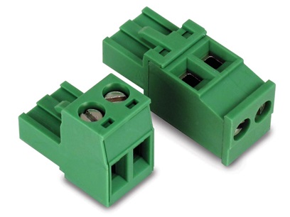
Straight and right angle AC input mating connectors are provided
Tables & Diagrams
500 Joules per second
(unit with internal fan)
DIMENSIONS: in.[mm]
REAR VIEW
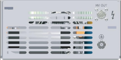
FRONT VIEW
BOTTOM VIEW
1000 Joules per second
(unit with internal and external fan)
DIMENSIONS: in.[mm]
REAR VIEW
FRONT VIEW
BOTTOM VIEW
Frequently Asked Questions
What Is a Safe Level of High Voltage?
Where Can I Obtain Information on High Voltage Safety Practices?
How Should I Ground Your Supply?
Why Do I Have to Fill Out a Capacitor Charging Questionnaire If I’m Going to Use Your Power Supply for Capacitor Charging?

