")
XRB150PN600 Monoblock® X-Ray Generators
- Integrated HV Supply, Filament Supply, X-Ray Tube, Beam Port and Control Electronics
- Compact & Lightweight
- Power Factor Corrected
- Can be Mounted in Any Physical Orientation
- Analog Monitoring and Standard RS-232 Digital Interface
*Note: All specifications are subject to change without notice. Please consult the English PDF version of this datasheet for the most up-to-date revision.
150kV, 600W X-Ray Source
Spellman’s XRB150PN600 Monoblock® X-Ray source is designed for OEM applications powering its internal X-Ray tube up to 150kV at 600W. Features like power factor correction, small package size and a standard analog and RS-232 digital interface simplify integrating this unit into your X-Ray system. Standard models are available with cone shaped beam geometry. Proprietary emission control circuitry provides excellent regulation of X-Ray tube current, along with outstanding stability performance.
Typical applications:
- X-Ray Scanning: Bone Densitometry
- Food Inspection
- Security
Specifications
(Ref. 128079-001 REV. G)
X-Ray Characteristics:
Tube Type: Glass tube, Tungsten target, Be filter
Focal Spot: 0.5mm x 0.5mm (IEC 336)
Beam Filter: 0.06. Ultem
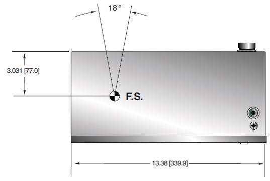
Beam Geometry: Cone up to 18° ±1°
Input Voltage:
Vac, 50/60Hz, 6.5A maximum 200-240 +/-10%
X-Ray Tube Voltage:
Nominal X-Ray tube voltage is adjustable between 70kV to 150kV
X-Ray Tube Current:
1.0mA to 4.0mA over specified tube voltage range
X-Ray Tube Power:
160W continuous, 600W peak Duty Cycle: 30 seconds on, 300 seconds off @ 600W peak
Voltage Regulation:
Line: ±0.1% for a ±10% input line change of 180 to 264Vac
Load: ±0.1% for a 1.0mA to 4.0mA load change. 600W maximum
Voltage Accuracy:
Voltage measured across the X-Ray tube is within ±2% of the programmed value
Voltage Risetime:
±1% in less than 300ms
Voltage Overshoot:
±10% during 300ms risetime
Voltage Ripple:
1% rms of rated voltage @ 10Hz to 1MHz
Current Regulation:
Line: ±0.1% from 180-264Vac
Load: ±0.5% @ 70-150kV, 1.0mA to 4.0mA
Current Accuracy:
Current measured through the X-Ray tube is within ±2% of the programmed value
Current Risetime:
±1% in less than 300ms
Arc Intervention:
4 arcs in 10 seconds with a 200ms quench = Shutdown
Filament Configuration:
Internal high frequency AC filament drive with closed loop filament emission control
Analog Interface:
0 to 5Vdc ground referenced signals
Digital Interface:
RS-232 interface.
Control Software:
A demo GUI for engineering evaluations will be provided for the RS-232 digital interface upon request.
Interlock/Signals:
A hardware interlock function is provided
Operating Temperature:
0°C to +40°C
Storage Temperature:
-40°C to +70°C
Humidity:
10% to 95% relative humidity, non-condensing
Cooling:
External fan required. 250cfm minimum to maintain an oil temperature of 55C° or less.
Input Line Connector:
3 pin Phoenix Contact P/N 1829167
Analog Interface Connector:
10 pin Phoenix Contact P/N 1755503
Digital Interface Connector:
9 pin D connector, female
Grounding Point:
8-32 ground stud provided on chassis
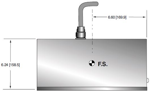
Dimensions:
13.46" X 13.38" X 6.24"
(341.89mm X 339.85mm X 158.50mm)
Weight:
66lbs (30kg)
Orientation:
Can be mounted in any orientation.
X-Ray Leakage:
Less than 100mR/hr at 1m distance, measured at 140kV, 3mA.
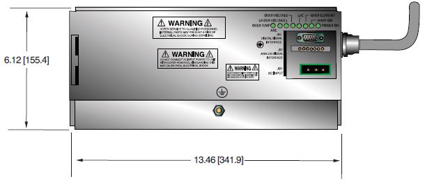
AC INPUT POWER JB1 3 PIN PHOENIX CONTACT
| Pin | Signal | Parameters |
|---|---|---|
| 1 | Line | Line |
| 2 | GND | Chassis Ground |
| 3 | Neutral | Neutral |
RS-232 DIGITAL INTERFACE— JB16 9 PIN FEMALE D CONNECTOR
| Pin | Signal | Parameters |
|---|---|---|
| 1 | Spare | N/C |
| 2 | Transmit | RS-232 |
| 3 | Receive | RS-232 |
| 4 | Spare | N/C |
| 5 | Signal Ground | Ground |
| 6 | Spare | N/C |
| 7 | Spare | N/C |
| 8 | Spare | N/C |
| 9 | Spare | N/C |
ANALOG INTERFACE— JB15 10 PIN PHOENIX CONTACT
| Pin | Signal | Parameters |
|---|---|---|
| 1 | X-Ray Signal | +12Vdc =Enable X-Ray, 0Vdc/open = Disable X-Ray, Zin=1kΩ |
| 2 | X-Ray Signal Return | Signal Return |
| 3 | N/C | N/C |
| 4 | kV Monitor | 0 to 5Vdc = 0 to 175kV, Zout= 10kΩ |
| 5 | Signal Ground | Signal Ground |
| 6 | mA Monitor | 0 to 5Vdc = 0 to 4.5mA, Zout= 10k |
| 7 | Fault Signal | Open collector, High (Open) = No Fault, 35Vdc @10mA maximum |
| 8 | HV ON Lamp Relay n/o | Relay Normally Open, 50Vdc @ 1A maximum |
| 9 | HV ON Lamp Relay common | Relay Common, 50Vdc @ 1A maximum |
| 10 | HV ON Lamp Relay n/c | Relay Normally Closed, 50Vdc @ 1A maximu |
LED INDICATORS
| Indicator | Signal Name | Condition Illuminated When... |
|---|---|---|
| LED 1 | OT | Over temperature occurs |
| LED 2 | ARC FLT | Arc fault occurs |
| LED 3 | UV | Low kV occurs |
| LED 4 | OV | High kV occurs |
| LED 5 | UC | Low mA occurs |
| LED 6 | OC | High mA occurs |
| LED 7 | X-RAY ON | X-Rays are enabled |
| LED 8 | PWR | Power is ON |
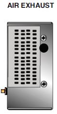
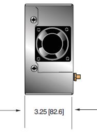
Tables & Diagrams
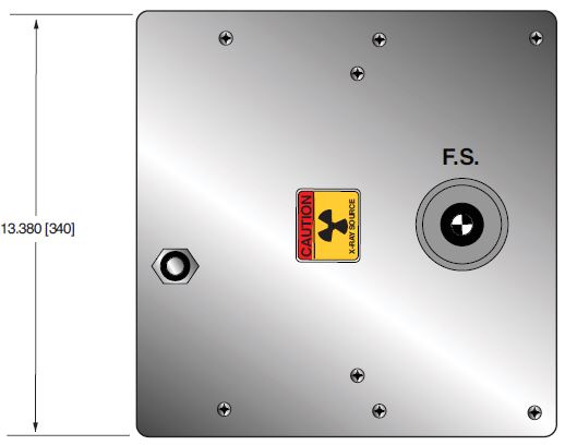
DIMENSIONS: in.[mm]
FRONT VIEW TANK
SIDE VIEW TANK
TOP VIEW TANK
FRONT VIEW
CONTROL ASSEMBLY
SIDE VIEW
CONTROL ASSEMBLY
SIDE VIEW
CONTROL ASSEMBLY
Frequently Asked Questions
Why Is Oil Insulation Used?
Do I Need to Ensure My Monoblock® Stays Cool? Why?
How Often Do I Need to Season My Monoblock® X-Ray Source? Why?
Application Notes AN-12 – The Benefit of Using a Current Source to Power X-Ray Tube Filament Circuits

