")
XRB011 Monoblock® X-Ray Generators
- Integrated HV Supply, Filament Supply, X-Ray Tube, Beam Port and Control Electronics
- Compact & Lightweight
- Can be Mounted in Any Physical Orientation
- Analog or Digital Control Interface
*Note: All specifications are subject to change without notice. Please consult the English PDF version of this datasheet for the most up-to-date revision.
![]()
80kV, 20-50W X-Ray Source
Spellman’s XRB011 Series of Monoblock® X-Ray sources are designed for OEM applications powering its internal X-Ray tube up to 80kV at 20W and 80kV at 50W. Features like 24Vdc input voltage, small package size, standard analog interface and RS-232/Ethernet digital interface simplify integrating the XRB011 into your X-Ray system. Proprietary emission control circuitry provides excellent regulation of X-Ray tube current, along with outstanding stability and performance.
Typical applications:
- Medical X-Ray: Fluoroscopy and Radiography for Extremities, Specimen Radiography.
- Pulsed Fluoroscopy (contact Spellman sales)
- Industrial X-Ray: Component inspection and Non-Destructive Testing
Specifications
(Ref. 128090-001 REV. AF)
X-Ray Characteristics:
Tube Type: Micro focus tube
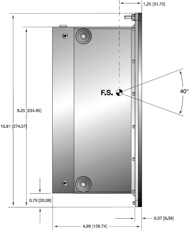
Focal Spot: 33µm Nominal, 50µm max. (IEC 336)
Beam Filter: Ultem 0.060. (1.5mm)
Oil 0.175. (4.4mm)
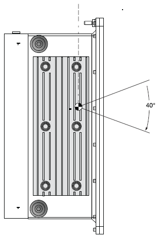
Beam Geometry: Symmetrical 40° cone
Input Voltage:
20W: 24Vdc ±1V @ 2.5A
50W: 24Vdc ±1V @ 4A
X-Ray Tube Voltage:
Nominal X-Ray tube voltage is adjustable between 35kV to 80kV
X-Ray Tube Current:
20W: 0-250µA over specified tube voltage range
50W: 0-700µA over specified tube voltage range
X-Ray Tube Power:
20/50W, maximum continuous
Voltage Regulation:
Line: ±0.5% for a ±1V change of nominal input line voltage
Load: ±0.1% for a load change of 25µA to maximum rated current
Voltage Accuracy:
Voltage measured across the X-Ray tube is within ±1% of the programmed value
Voltage Risetime:
Ramp time shall be =250ms from 10% to 90% of maximum rated output voltage
Voltage Temperature Coefficient:
≤100ppm/°C
Over Temperature Fault:
Indicates that the internal oil temperature has exceeded 65° C. The high voltage output will be disabled. Toggling the X-Ray ON Command OFF and ON will reset the fault.
Over Voltage Fault:
An overvoltage (OV) fault is detected when the output voltage exceeds 82kV. The high voltage output will be disabled. Toggling the X-Ray ON Command OFF and ON will reset the fault.
Voltage Ripple:
1% peak to peak
Current Regulation:
Line: ±0.5% for a ±1V change of nominal input line voltage
Load: ±0.5% for a voltage change of 35kV to 80kV
Current Accuracy:
Current measured through the X-Ray tube is within ±2.5% of the programmed value
Over Current Fault:
An overcurrent (OC) fault is detected when the emission current exceeds 275µA (20W model) and 710µA (50W model). Toggling the X-Ray ON Command OFF and ON will reset the fault.
Arc Intervention:
One arc fault. The high voltage output will be disabled. Toggling the X-Ray ON command OFF and ON will reset the fault.
Filament Configuration:
Internal high frequency AC filament drive with closed loop filament emission control
Analog Interface:
Ground referenced 10kV/V, 25µA/V (20W model) and 70µA/V (50W model) for programming and monitoring analog interface signals. Open collector, active low digital signal interface. Internal jumper is needed to be configured for analog interface.
Digital Interface:
RS-232: standard
Ethernet: optional
Control Software:
A demo GUI is available for engineering evaluations Interlock/Signals: A hardware interlock functions in both analog and digital programming modes.
Operating Temperature:
0°C to +40°C
Storage Temperature:
-20°C to +70°C
Humidity:
10% to 95% relative humidity, non-condensing
Cooling:
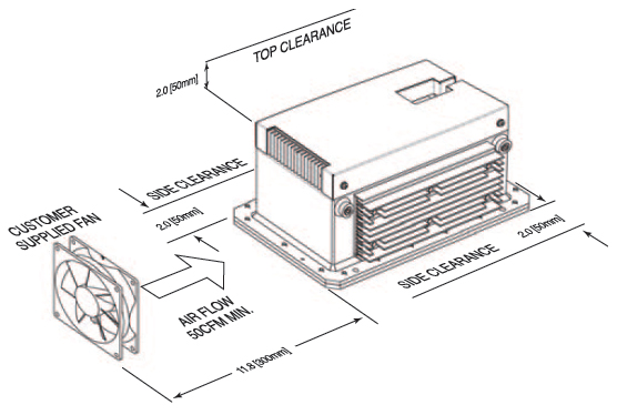
20W and 50W option: Customer provided, external cooling fan, 50cfm, minimum.
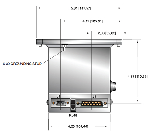
Analog Interface and Input Line Connector:
25 pin D connector, male
Digital Interface Connector:
RS-232: 9 pin D connector, female
Ethernet: RJ45 connector
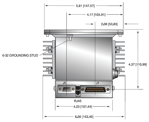
Grounding Point:
6-32 ground stud provided on chassis
Dimensions:
20W: 5.81"W X 5.0"H X 10.81"D (147.57mm X 127mm X 274.57mm)
50W: 6.00"W X 5.0"H X 10.81"D (152.4mm X 127mm X 274.57mm)
Weight:
20W: 18lbs (8.165kg)
50W: 20lbs (9.072kg)
Orientation:
Can be mounted in any orientation.
X-Ray Leakage:
Less than 1mR/hr at 1 meter
Regulatory Approvals:
Compliant to UL/CUL recognized file E242584. CE to EN 61010-1 for non-medical applications.
RS-232 DIGITAL INTERFACE— J5 9 PIN FEMALE D CONNECTOR
| Pin | Signal | Parameters |
|---|---|---|
| 1 | NC | No Connection |
| 2 | TX Out | Transmit Data |
| 3 | RX In | Receive Data |
| 4 | NC | No Connection |
| 5 | SGND | Signal Ground |
| 6 | NC | No Connection |
| 7 | NC | No Connection |
| 8 | NC | No Connection |
| 9 | NC | No Connection |
ETHERNET DIGITAL INTERFACE— RJ45 8 PIN CONNECTOR
| Pin | Signal | Parameters |
|---|---|---|
| 1 | TX + | Transmit Data + |
| 2 | TX -t | Transmit Data - |
| 3 | RX + | Receive Data + |
| 4 | NC | No Connection |
| 5 | NC | No Connection |
| 6 | RX | Receive Data - |
| 7 | NC | No Connection |
| 8 | NC | No Connection |
ANALOG INTERFACE— J1 25 PIN MALE D CONNECTOR
| Pin | Signal | Parameters |
|---|---|---|
| 1 | +24V | +24Vdc±1Vdc @ 4A |
| 2 | +24V | +24Vdc±1Vdc @ 4A |
| 3 | +24V | +24Vdc±1Vdc @ 4A |
| 4 | NC | No Connection |
| 5 | +24V RETURN | +24V RETURN |
| 6 | +24V RETURN | +24V RETURN |
| 7 | +24V RETURN | +24V RETURN |
| 8 | Signal Ground | Signal Ground |
| 9 | Interlock Input | Input, Active low, Interlock is low safe to enable high voltage. Connect to +24V Return |
| 10 | kV Monitor | Output, 0 to 8V = 0 to rated output voltage. Zout=100Ω |
| 11 | μA Monitor | Output, 0 to 10V = 0 to rated output current. Zout=100Ω |
| 12 | X-Ray Ready status | Output, Active Low, Open Collector, 24Vdc @ 10mA max |
| 13 | X-Ray ON status | Output, Active Low, Open Collector, 24Vdc @ 10mA max |
| 14 | Filament Standby status | Output, Active Low, Open Collector, 24Vdc @ 10mA max |
| 15 | Over Voltage Fault | Output, Active Low, Open Collector, 24Vdc @ 10mA max |
| 16 | Over Current Fault | Output, Active Low, Open Collector, 24Vdc @ 10mA max |
| 17 | ARC Fault | Output, Active Low, Open Collector, 24Vdc @ 10mA max |
| 18 | Filament Current Limit Faul | Output, Active Low, Open Collector, 24Vdc @ 10mA max |
| 19 | Signal Ground | Signal Ground |
| 20 | Interlock Output | Output, Active Low, Open Collector, 24Vdc @ 10mA max |
| 21 | μA Program | Input, 0 to 10V = 0 to rated output current. Zin=10kΩ |
| 22 | kV Program | Input, 0 to 8V = 0 to rated output voltage. Zin=10kΩ |
| 23 | X-Ray ON Command | Input, Active low Low (short) = X-Ray ON High (open) = X-Ray OFF Internal pull up resistor to +15V |
| 24 | Signal Ground | Signal Ground |
| 25 | Over Temperature | Active Low, Open Collector, 24Vdc @ 10mA max |
Tables & Diagrams
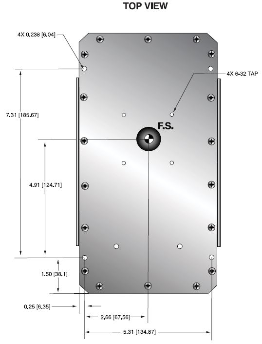
DIMENSIONS: in.[mm]
20W Model
ORDERING INFORMATION
Medical Applications:
XRB011-80PN20 80kV, 250uA, 20W, Analog Interface, RS-232
XRB011-80PN20E 80kV, 250uA, 20W, Analog Interface, RS-232, Ethernet
XRB011-80PN20A 80kV, 250uA, 20W, Analog Interface
Non-Medical Applications:
XRB011-80PN20/CE 80kV, 250uA, 20W, Analog Interface, RS-232, CE
XRB011-80PN20E/CE 80kV, 250uA, 20W, Analog Interface, RS-232, Ethernet, CE
XRB011-80PN20A/CE 80kV, 250uA, 20W, Analog Interface, CE
SIDE VIEW
FRONT VIEW
TOP VIEW
50W Model
ORDERING INFORMATION
Medical Applications:
XRB011-80PN50 80kV, 700uA, 50W, Analog Interface, RS-232
XRB011-80PN50E 80kV, 700uA, 50W, Analog Interface, RS-232, Ethernet
XRB011-80PN50A 80kV, 700uA, 50W, Analog Interface
Non-Medical Applications:
XRB011-80PN50/CE 80kV, 700uA, 50W, Analog Interface, RS232, CE
XRB011-80PN50E/CE 80kV, 700uA, 50W, Analog Interface, RS232, Ethernet, CE
XRB011-80PN50A/CE 80kV, 700uA, 50W, Analog Interface, CE
SIDE VIEW
FRONT VIEW
TOP VIEW
Frequently Asked Questions
Why Is Oil Insulation Used?
Do I Need to Ensure My Monoblock® Stays Cool? Why?
How Often Do I Need to Season My Monoblock® X-Ray Source? Why?
Application Notes AN-12 – The Benefit of Using a Current Source to Power X-Ray Tube Filament Circuits

