")
VMX Series
- Custom Designed Specifically for Mammography Applications
- Fast Settling Helps Minimize Patient Radiation Exposure
- Dual Speed Starter, Boost/Brake Capability
- RS-232 and Optional Ethernet Interfaces
- Low Cost, Value Added, Modular Design
*Note: All specifications are subject to change without notice. Please consult the English PDF version of this datasheet for the most up-to-date revision.

40kV/5kW Mammography X-Ray Generators
Spellman’s VMX redefines the standard for high performance, low cost Mammography X-Ray generators. The VMX was born from an integrated, high performance, value added design perspective so there’s no need to compromise critical specifications to meet ever demanding system price targets.
The 40kV/5kW X-Ray generator integrates a dual filament power supply and a dual speed starter. A DC current source filament power supply provides fast rise times with stable and accurate X-Ray tube emission currents. The solid encapsulated high voltage output section eliminates oil concerns while reducing the effects of environmental humidity and contamination.
Flexibility in interfacing is provided via RS-232 and optional Ethernet connectivity. The VMX supports advanced mammography application features including Smart AEC Exposure, Automatic Filament Calibration, Tube Anode Heat Calculator and user configurable Tube Library. Compact, full featured,high performance, low cost. Spellman’s VMX, the next generation Mammography X-Ray generator.
Specifications
(Ref. 128092-001 REV. L)
Input Voltage:
200-240Vac (±10%), single phase, 50Hz/60Hz
Input Current:
Minimum 35A service recommended for 5kW operation
External EMC Filter (Schaffner FN2070-36-08-36A) required to meet CE/EMC specifications – Not provided with the generator
Mains Contactor – Not provided within the generator. Customer is responsible for mains safety disconnection.
Output Voltage
Output Voltage Range: 20kV to 40kV
Polarity: Positive, grounded cathode X-Ray tube
Accuracy: Within 1% of programmed values
Reproductibility: <0.5%
Settling Time: <10ms
Ripple: ≤ 1%
Stability: ≤ 0.01% per 8 hours
Temperature Coefficient: ≤ 100ppm/°C
Output Current/Power
Output Current Range: 10mA to 200mA
Output Power: 5kW @ 0.1 second loading time
Maximum mAs:
600mAs
Exposure Timer:
5ms-10 seconds
Accuracy:
Within 2% of programmed values measured after mA rises to stable DC level
Reproductibility:
<0.5%
Settling Time:
<10ms
Filament Configuration:
DC filament drive: self corrected filament preheat settings with closed loop emission control and smart learning algorithm
Filament Output:
0-6 amps at a compliance of 5.5 volts, maximum
Dual Speed Starter:
High speed (180Hz) and low speed (60Hz) can be configured via the serial interface.
Boost and Brake capability provided.
High Voltage Connector:
60kV, Claymount CA-3 type or equivalent
Optional Communication Interface:
Ethernet (RJ45)
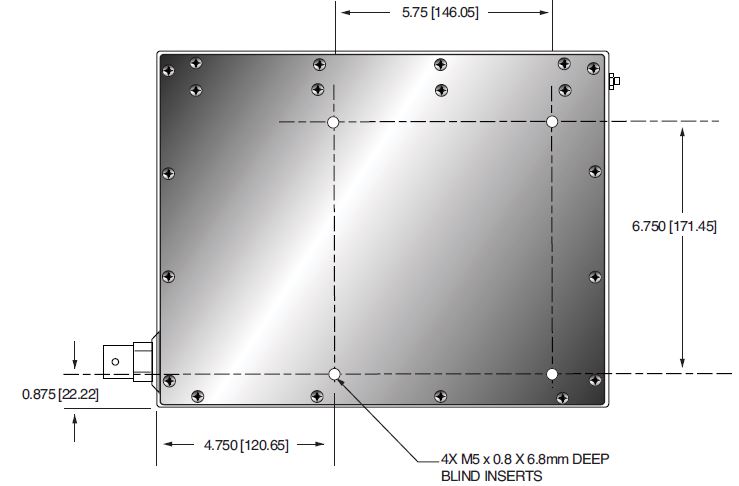
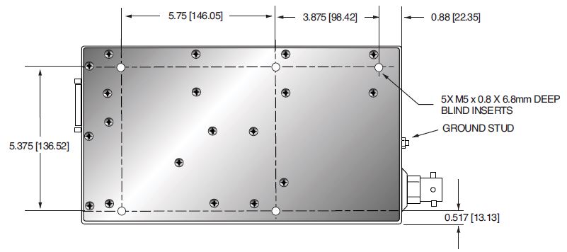
Grounding Point:
M5 ground stud provided on chassis
Environmental:
Temperature Range:
Operating: 10°C to 40°C
Storage: -40°C to 85°C
Humidity:
20% to 85% RH, non-condensing.
Cooling:
Convection cooled, no internal fans. Forced air cooling not required
Dimensions:
9.38. H X 6.6. W X 12. D (237.5mm x 167.6mm x 304.8mm)
Weight:
<22 pounds (10kg
Regulatory Approvals:
Compliant to EMC:IEC 60601-1-2. UL/CUL recognized file E242584. RoHS compliant.
Application Features:
- 2 point/3 point exposure modes
- AEC/Smart AEC exposure modes
- Automatic filament current calibration
- Tube anode heat calculator
- User configurable tube library
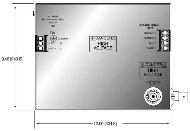
TB2 ROTOR INTERFACE
| Pin | Signal | Parameters |
|---|---|---|
| TB2-1 | PHASE | To tube auxiliary winding |
| TB2-2 | RUN | To tube principle winding |
| TB2-3 | COM | To tube common winding |
| TB2-4 | GROUND | To tube housing ground |
TB3 TUBE AND INTERLOCK INTERFACE
| Pin | Signal | Parameters |
|---|---|---|
| TB3-1 | SMALL FIL | Connection to tube small filament |
| TB3-2 | COMMON | Connection to tube filament common |
| TB3-3 | LARGE FIL | Connection to large filament |
| TB3-4 | GROUND | Generator chassis for cable shield connection |
| TB3-5 | Interlock 2+ | Used if tube has separate thermostat switch. Open = OVER TEMP. (short terminals if not used) |
| TB3-6 | Interlock 2- | Used if tube has separate thermostat switch. Open = OVER TEMP. (short terminals if not used) |
| TB3-7 | Interlock 3+ | Used if tube has cooling circulator flow switch. Open = NO FLOW. (short terminals if not used) |
| TB3-8 | Interlock 3- | Used if tube has cooling circulator flow switch. Open = NO FLOW. (short terminals if not used) |
| TB3-9 | Safety Interlock+ | User signal (Contact Closure) for safety interlocks such as door interlocks. Open turns HV OFF, or inhibits HV from being generated. Closed = OK 24Vdc @ <1A typical |
| TB3-10 | Safety Interlock- | User signal (Contact Closure) for safety interlocks such as door interlocks. Open turns HV OFF, or inhibits HV from being generated. Closed = OK 24Vdc @ <1A typical |
| TB3-11 | Contactor Coil+ | Option for contactor coil control |
| TB3-12 | Contactor Coil- | Option for contactor coil control |
| TB3-13 | Spare | N/C |
| TB3-14 | Spare | N/C |
| TB3-15 | Tube Current+ | Tube current flows out from this pin |
| TB3-16 | Tube Current- | Tube current flows into this pin |
VMX STANDARD SYSTEM INTERFACE—JB1 25 PIN MALE D CONNECTOR
| Pin | Signal | Parameters |
|---|---|---|
| 1 | GND | Signal Ground |
| 2 | +5Vdc Out | +5Vdc, 100mA max. |
| 3 | RS-232 Tx Out | RS-232 Transmit |
| 4 | RS-232 Rx In | RS-232 Receive |
| 5 | PREP | User signal (Contact Closure) to alert the generator that exposure sequence will begin. Once this signal is active, exposure parameters are locked in and cannot be changed. The generator enables the starter to to boost the rotor. Contact connection to pin 24. Closed = PREP, the filament is placed in preheat mode |
| 6 | READY | Generator signal to user to indicate the rotor runs to speed and the generator is ready for X-Ray exposure Open Collector. Low/Active = Ready |
| 7 | ROTOR SHUTDOWN | User signal to brake the rotor drive |
| 8 | EXPOSURE | User signal (Contact Closure) to generator to generate X-Rays. Filament is boosted, and high voltage is generated after the boost time. Contact connection to pin 24. Closed = Exposure |
| 9 | X-Ray ON 75% Status | Transistor output to indicate X-Ray ON status synchronized with 75% of kVP setting point. |
| 10 | X-Ray ON Status | Transistor output to indicate X-Ray ON status synchronized with kV start up. |
| 11 | N/C | N/C |
| 12 | X-Ray SHUTDOWN/AEC | User signal to generator to rapidly turn HV OFF and ON during serial exposure sequence |
| 13 | RS-232 ISO Ground | Isolated ground from RS-232 transceiver IC |
| 14 | HVG FAULT Status | Generator signal indicating generator fault. Open collector transistor output. Low/Active = Fault |
| 15 | Status Bit 1 | 3 bit status lines for up to 6 status messages. See separate matrix descibing functionality. Open Collector. Low/Active = Message |
| 16 | Status Bit 2 | |
| 17 | Status Bit 3 | |
| 18 | N/C | N/C |
| 19 | N/C | N/C |
| 20 | kV Monitor | Signal from generator. 0-10V = 0-40kV. Zout = 1kΩ |
| 21 | Emission Monitor | Signal from generator. 0-10V = 0-200mA. Zout = 1kΩ |
| 22 | Filament Current Monitor | Signal from generator. 0-10V = 0-6A. Zout = 1kΩ |
| 23 | Program/Monitor Return | Ground for reference of program and monitor signals |
| 24 | +24Vdc Out | For connection to PREP and EXPOSURE control relay coils |
| 25 | SHIELD/GND | For connection of interface cable shield to generator chassis ground |
Tables & Diagrams
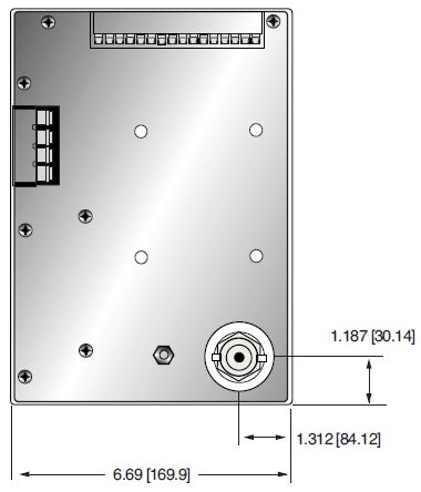
DIMENSIONS: in.[mm]
FRONT VIEW
TOP VIEW
BOTTOM VIEW
SIDE VIEW
Frequently Asked Questions
Application Notes AN-12 – The Benefit of Using a Current Source to Power X-Ray Tube Filament Circuits
Application Notes AN-01 – Fundamentals of X-Ray Generator – X-Ray Tube Optimization

