MSA Series
- Compact High Performance Module
- Variable Voltage Programming
- 0.9 Watts Output Power
- Voltage Monitor
- Arc and Short Circuit Protected
*Note: All specifications are subject to change without notice. Please consult the English PDF version of this datasheet for the most up-to-date revision.

MSA
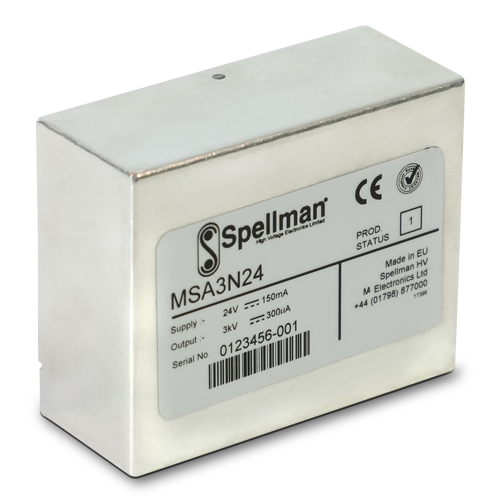
The MSA Series are compact printed circuit board mountable (PCB) high voltage power supply module available from 1kV to 3kV with either a positive or negative output polarity. The MSA Series feature 0-10Vdc variable voltage programming that equals 0-100% of rated output voltage. A voltage monitor is provided where 0-10Vdc equals 0-100% of rated output voltage. Additionally a status signal and enable signal provides simple control of the power supply. All units have in-built protection against fault conditions.
The MSA Series are intended for general use where a compact high performance PCB mountable power supply is required, like driving an electron multiplier in a mass spectrometer. The aluminium enclosure helps shield the unit reducing radiated noise.
Typical applications:
- Photomultiplier Tubes
- Electron Multiplier
- Mass Spectrometry
- Electrostatic Lenses
- Nuclear Instruments
Specifications
(Ref. 128018-001 REV. D)
SPECIFICATIONS
Input Voltage:
+24 Vdc, ±2Vdc
Input Current:
150mA maximum input current
30mA pk-pk maximum input current ripple
Output Polarity:
Positive or negative, specify at time of order
Output Power:
0.9 watts, maximum
Output Voltage Accuracy:
±1%
Voltage Regulation:
Line: 21.6Vdc to 26.4Vdc, ±0.02%
Load: 0-100% rated load, ±0.02%
Stability: 50ppm/8hrs after one hour warm up period
Temperature Coefficient:
25ppm per degree C
Settling Time: After Power On or Enable
100 milliseconds, typical
When power is removed the unit will decay to <±60 volts within 2 seconds
Protection:
Arc and short circuit protected.
Not designed to withstand continuous arcing
Environmental:
Temperature Range:
Operating: 0˚C to 60˚C
Storage: -20˚C to 70˚C
Humidity:
95% RH, non-condensing
Cooling: Convection cooled
Dimensions:
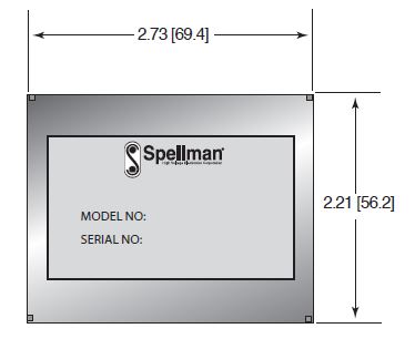
2.73˝ L x 2.21˝ W x 1.21˝ D (69.4mm x 56.2mm x 30.7mm)
Weight:
7.0 oz. (200g)
Regulatory Approvals:
Designed to meet EN 61010-1, UL 61010A-1 and CAN/CSA-22.2 No. 61010.1 As the unit is intended for incorporation into end users equipment it will not be tested as a standalone unit to meet the EMC directive. The user will need to follow sensible EMC precautions in using the unit. The unit is compliant with the EU RoHS directive
MSA SELECTION TABLE
| Model | Output Voltage | Output Current | Ripple (Vpp) |
|---|---|---|---|
| MSA1*24 | 0-1kV | 0-900μA | 30mV |
| MSA2*24 | 0-2kV | 0-450μA | 40mV |
| MSA3*24 | 0-3kV | 0-300μA | 50mV |
1) Replace the * with “P” for positive output polarity and “N” for negative output polarity.
2) The ripple figure includes random non switch related noise, noise related to the oscillator, switching and feedback control circuitry and noise associated with the rectified primary switching frequency.
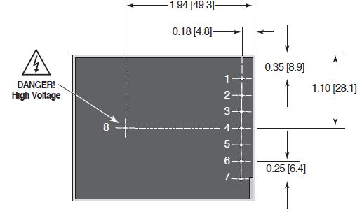
LOW VOLTAGE SIGNAL PINS FOR POWER AND CONTROL
| PIN | SIGNAL | LEVEL | SIGNAL PARAMETERS |
|---|---|---|---|
| 1 | Enable | TTL | Enable = Low (≤1.2V). Disable = High (≥2.4V), when Enable pin is NC, 10kΩ pull up to +5V ±10% |
| 2 | Status | 0V/5V | OK = 11kΩ pull up to +5.1V ±10%. Fault = ≤0.1V, Zout = 1kΩ |
| 3 | Voltage Program | 0-10V | 0 to +10Vdc = 0 to 100% rated output voltage, Accuracy ≈ ±1%. Zin = 10kΩ |
| 4 | Voltage Monitor | 0-10V | 0 to +10Vdc = 0 to 100% rated output voltage, Accuracy = ±2%. Zout = 20kΩ |
| 5 | Input Voltage | 24Vdc | Power Input |
| 6* | Signal Ground | 0V | Ground reference for control and monitoring signals |
| 7* | Power Ground | 0V | Power Return |
To reset the unit after a fault condition, Pin1 (Enable) must be set high for at least 10 seconds
* pins 6 & 7 are linked internally
HIGH VOLTAGE CONNECTION DETAIL
| PIN | SIGNAL | SIGNAL PARAMETERS |
|---|---|---|
| 8 | High Voltage Output | 0-100% Rated Output. !!Danger: High Voltage!! |
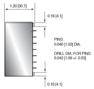
Tables & Diagrams
DIMENSIONS: in.[mm]
TOP VIEW
FRONT VIEW
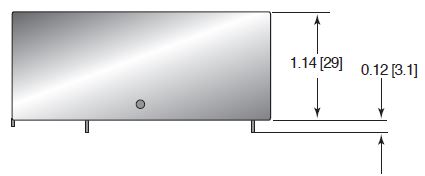
BOTTOM VIEW
SIDE VIEW
Frequently Asked Questions
What Is a Safe Level of High Voltage?
Where Can I Obtain Information on High Voltage Safety Practices?
How Should I Ground Your Supply?
Why Is Arcing an Issue for a High Voltage Power Supply?

