MI1.5PN24
- Floating, Programmable 1.5kV Output
- Well Regulated, Low Ripple
- Low Z Output Network for Pulsed Load Applications
- Compact Design
*Note: All specifications are subject to change without notice. Please consult the English PDF version of this datasheet for the most up-to-date revision.
Mass Spec Power Supply
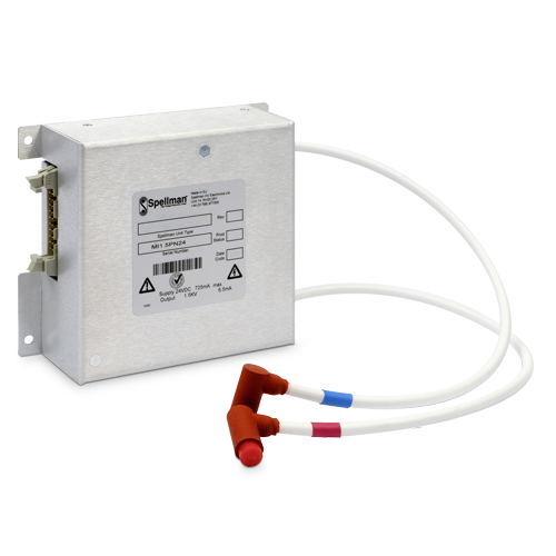
Spellman’s MI1.5PN24 is a well-regulated, high performance DC-DC converter featuring a floating 1.5kV @ 6.5mA output, it has an operational range 300V-1500V. The output is isolated; this allows connection to loads of +Ve, -Ve or switchable polarity and for pulse currents to be contained within prescribed paths, reducing noise and interference signatures. The MI1.5PN24 low output ripple specification makes it ideal for use with pulsers in Mass Spectrometry applications. This module is packaged in a shielded metal enclosure and the high voltage output is provided via two captive cables. The MI1.5PN24 has a large, high quality capacitance and rugged output network, this allows high energy pulsed loads to powered continuously without significant voltage drop or damage to the unit circuitry. The unit has remote 0-10Vdc = 0-100% rated voltage programming and voltage monitor. A TTL compliant Enable signal provides simple control of the high voltage output.
Specifications
(Ref. 128154-001 REV.A)
Input Voltage:
+24Vdc, ±10%. Protected against reverse connection
Input Current:
725mA maximum at 1500V @ 6.5mA
Output Voltage:
300V to 1.5kV, continuously variable over entire output range
Polarity:
Positive or negative, isolated to 1.5kV
Load Current:
6.5mA, maximum
Power:
9.75 watts, maximum
Regulation:
Line: <0.5% for line change of ±10%
Load: <0.1% for zero to full load
Stability:
Better than 300ppm/hour after 1 hour warm up. 100ppm/hour after 2 hour warm up at constant operating conditions. Typically, 50ppm/hour after 1 hour and 15ppm/hour after 2 hours.
Temperature Coefficient:
<100ppm/°C, typically 25ppm/°C
Ripple:
<75mV peak to peak at full load when either end is grounded.
Output Current Limit:
The module will have an output current limit of 9mA. The module is capable of withstanding an indefinite short circuit or overload on its output and will recover automatically once the short circuit is removed.
Supply Voltage Dynamic Rejection:
< than 20mV for an input step of 1 volt (within the range of +24Vdc, +10%/-2%)
Setting Time:
500 milliseconds maximum under all conditions.
Output Capacitance:
>400nF - Connected directly between POSITIVE to NEGATIVE output nodes
Environmental:
Temperature Range:
Operating: +15°C to +50°C
Storage: -40°C to 70°C
Humidity: 5% to 95% RH @ 40°C non-condensing
Cooling:
Convection cooled
Interface Connector:
20 pin IDC male connector
High Voltage Output Connectors:
Two Varex CA166 (Connectronics SCID compatible) right angle connectors, 10 inches (254mm) long. The +Ve cable will have a RED band and “POS” printed on the cable. The -Ve cable will have a BLUE band and “NEG” printed on the cable. High voltage outputs are floating.
Star Ground Network:
+24Vdc Return is central; case, analog input ground and digital ground are returned through a 100Ω resistor in parallel with a 0.001uF capacitor to the +24Vdc Return.
Dimensions:
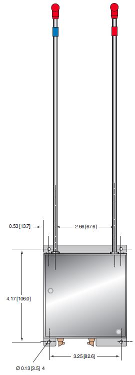
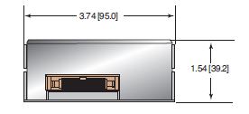
4.53”L x 3.74”W x 1.54”D (115mm X 95mm X 39.2mm)
Weight:
0.66lbs. (0.3kg)
Regulatory Approvals:
The unit is CE marked. The unit has been designed to meet the requirements of EN61010, UL1950 and CSA 22.2 No. 950.
EMC:
As the unit is a component it will not be tested as a stand alone unit to meet the EMC directive. The user will need to follow sensible EMC precautions in using the unit.
INTERFACE CONNECTOR — 20 PIN IDC MALE CONNECTOR
| PIN | SIGNAL | SIGNAL PARAMETERS |
|---|---|---|
| 1 | Voltage Control Return | Analog Ground |
| 2 | Voltage Control* | 0Vdc to +10Vdc = 0 to 1.5kV (differential Input) Zin = 100kΩ. Protected against inputs of <11 volts and reverse voltages. |
| 3 | Voltage Control Return | Analog Ground |
| 4 | N/C | No Connection |
| 5 | Voltage Control Return | Analog Ground |
| 6 | N/C | No Connection |
| 7 | Voltage Control Return | Analog Ground |
| 8 | N/C | No Connection |
| 9 | Voltage Control Return | Analog Ground |
| 10 | Voltage Monitor | +2Vdc to +10Vdc = 300 volts to 1.5kV, ±1%, Zout = 1kΩ |
| 11 | N/C | No Connection |
| 12 | Enable | TTL: Low = HV ON. Referenced to +24Vdc Return. |
| 13 | N/C | No Connection |
| 14 | N/C | No Connection |
| 15 | N/C | No Connection |
| 16 | N/C | No Connection |
| 17 | +24Vdc Return | Power Return (Power Ground) |
| 18 | +24Vdc Power | +24Vdc @ 725mA |
| 19 | +24Vdc Return | Power Return (Power Ground) |
| 20 | +24Vdc Power | +24Vdc @ 725mA |
*At voltage programming voltages less than 2 volts, parameters in this specification may not be met.
| How to Order: |
|---|
| Standard: PART NO.: MI1.5PN24 |
Tables & Diagrams
DIMENSIONS: in.[mm]
TOP VIEW
SIDE VIEW
FRONT VIEW


