")
MFX Series
- 50kV with 50 or 75 Watt Max
- 65kV with 65 Watt Max
- Floating Integrated Filament Supply
- Local and Remote Emission Control
- Optional Digital Interface
*Note: All specifications are subject to change without notice. Please consult the English PDF version of this datasheet for the most up-to-date revision.

50-75W Industrial X-Ray Generators
The MFX Series is the result of Spellman’s exceptional high voltage packaging and surface mount fabrication techniques, coupled with its proprietary encapsulation technology producing this ultra compact-sized OEM X-Ray generator module.
The MFX Series is designed to power floating filament X-Ray tubes from various manufacturers. It features a 0 to 50kV (or 0 to 65kV) high voltage output, and up to 2mA of emission current limited to 50, 65 or 75 Watts, operating from a +24Vdc input. The MFX utilizes a closed loop filamentry beam control circuit to provide a highly regulated beam current. The floating ac filament supply operates between 0.3 and 4 amps. Offering tight regulation, high stability and low ripple, the MFX provides users both local and remote analog control to set beam voltage, emission current and filament current limit. An optional USB, RS-232 and Ethernet interface is available.
Specifications
(Ref. 128101-001 REV. K)
J2 POWER INPUT CONNECTOR
| Pin | Signal | Parameters |
|---|---|---|
| 1 | +24V Input | +24 volts @ 5A, max. |
| 2 | 24V Return (Gnd.) | Power Ground |
J4 ANALOG INTERFACE CONNECTOR MALE 15 PIN MINI "D"
| Pin | Signal | Parameters |
|---|---|---|
| 1 | Monitor Return | Signal Ground |
| 2 | Voltage Monitor | 0-10 volts = 0 to full scale, Zout=1KΩ |
| 3 | Current Monitor | 0-10 volts = 0 to full scale, Zout=1KΩ |
| 4 | Interlock Output | Connect 12V HVON bulb to pin 15 to enable |
| 5 | +10 Volt Reference | +10 Volts @ 1mA, maximum |
| 6 | Filament Monitor | 1 volt = 1 amp, Zout=1KΩ |
| 7 | Voltage Program Input | 0-10 volts = 0 to full scale, Zin=10MΩ |
| 8 | Local Voltage Program* | 10 turn pot., screwdriver adjust |
| 9 | Filament Limit Setpoint* | 1 volt = 1 amp, screwdriver adjust |
| 10 | Current Program Input | 0-10 volts = 0 to full scale, Zin=10MΩ |
| 11 | Local Current Program* | 10 turn pot, screwdriver adjust |
| 12 | Not used (+24V Out for Interlock) | (Optional Interlock configuration) |
| 13 | Not used (Interlock Coil) | (Optional Interlock configuration) |
| 14 | Filament Preheat Setpoint* | 1 volt = 1 amp, screwdriver adjust |
| 15 | Interlock Return | Interlock Ground |
*Denotes 10 turn potentiometer located on front panel
J1 CATHODE OUTPUT CLAYMOUNT HV CONNECTOR
| Pin | Output Connection |
|---|---|
| C (common) | -High Voltage Output |
| S (small) | -High Voltage Output |
| L (large) | Filament Output |
| G (grid) | Filament Output |
Note: No high voltage cable is provided
Recommended Cable:
Claymount part number: 11470
Cable assembly, L3 CA11, CA11, 10F, CS=Bare 10 foot, Mini Federal Connectors on both ends, "C" and "S" are both connected to the bare wire
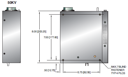
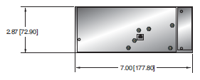
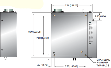
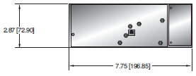
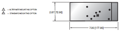
Tables & Diagrams
DIMENSIONS: in.[mm]
50KV
50KV WITH SIC OPTION
65KV
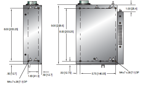
65KV WITH SIC OPTION

Frequently Asked Questions
Application Notes AN-12 – The Benefit of Using a Current Source to Power X-Ray Tube Filament Circuits
Application Notes AN-01 – Fundamentals of X-Ray Generator – X-Ray Tube Optimization

