SERIE MFX
- 50KV con 50 o 75 vatios máx
- 65 kv con 65 vatios máx.
- Suministro de filamento integrado flotante
- Control de emisiones local y remota
- Interfaz digital opcional
*Nota: Todas las especificaciones están sujetas a cambios sin previo aviso. consulte la versión en inglés en PDF de esta hoja de datos para obtener la revisión más actualizada
GENERADORES DE RAYOS X INDUSTRIALES DE 50 W-75 W
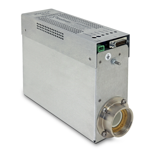
La serie MFX es el resultado de las técnicas de fabricación excepcionales de empaquetado de alto voltaje y montaje superficial de Spellman en conjunto con su tecnología de encapsulamiento de diseño propio, lo cual produce el diseño ultra compacto de este módulo generador de rayos X para aplicaciones de OEM.
La serie MFX está diseñada para energizar tubos de rayos X de filamento flotante de distintos fabricantes. Está equipada con salida de alto voltaje de 0 kV a 50 kV (o 0 kV a 65 kV) y hasta 2 mA de corriente de emisión limitada a 50 W, 65 W o 75 W y operando con +24 VCD de entrada. La MFX utiliza un circuito de control de filamento de lazo cerrado para proporcionar una corriente de haz altamente regulada. La alimentación del filamento de CA flotante opera entre 0.3 A y 4 A. Ofreciendo una regulación precisa, altamente estable y de bajo rizo, la MFX proporciona a los usuarios el control analógico local y remoto para ajustar el voltaje del haz, la corriente de emisión y el límite de la corriente del filamento. Opcionalmente, están disponibles las interfaces RS-232 y Ethernet.
Especificaciones
(Ref. 128101-001 REV. K)
J2 POWER INPUT CONNECTOR
| Pin | Signal | Parameters |
|---|---|---|
| 1 | +24V Input | +24 volts @ 5A, max. |
| 2 | 24V Return (Gnd.) | Power Ground |
J4 ANALOG INTERFACE CONNECTOR MALE 15 PIN MINI "D"
| Pin | Signal | Parameters |
|---|---|---|
| 1 | Monitor Return | Signal Ground |
| 2 | Voltage Monitor | 0-10 volts = 0 to full scale, Zout=1KΩ |
| 3 | Current Monitor | 0-10 volts = 0 to full scale, Zout=1KΩ |
| 4 | Interlock Output | Connect 12V HVON bulb to pin 15 to enable |
| 5 | +10 Volt Reference | +10 Volts @ 1mA, maximum |
| 6 | Filament Monitor | 1 volt = 1 amp, Zout=1KΩ |
| 7 | Voltage Program Input | 0-10 volts = 0 to full scale, Zin=10MΩ |
| 8 | Local Voltage Program* | 10 turn pot., screwdriver adjust |
| 9 | Filament Limit Setpoint* | 1 volt = 1 amp, screwdriver adjust |
| 10 | Current Program Input | 0-10 volts = 0 to full scale, Zin=10MΩ |
| 11 | Local Current Program* | 10 turn pot, screwdriver adjust |
| 12 | Not used (+24V Out for Interlock) | (Optional Interlock configuration) |
| 13 | Not used (Interlock Coil) | (Optional Interlock configuration) |
| 14 | Filament Preheat Setpoint* | 1 volt = 1 amp, screwdriver adjust |
| 15 | Interlock Return | Interlock Ground |
*Denotes 10 turn potentiometer located on front panel
J1 CATHODE OUTPUT CLAYMOUNT HV CONNECTOR
| Pin | Output Connection |
|---|---|
| C (common) | -High Voltage Output |
| S (small) | -High Voltage Output |
| L (large) | Filament Output |
| G (grid) | Filament Output |
Note: No high voltage cable is provided
Recommended Cable:
Claymount part number: 11470
Cable assembly, L3 CA11, CA11, 10F, CS=Bare 10 foot, Mini Federal Connectors on both ends, "C" and "S" are both connected to the bare wire
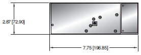
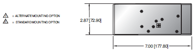
Tablas y Diagramas
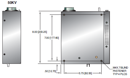
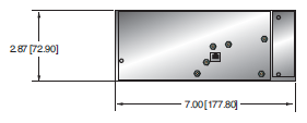
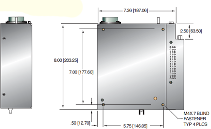
DIMENSIONS: in.[mm]
50KV
50KV WITH SIC OPTION
65KV
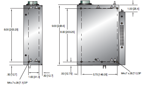
65KV WITH SIC OPTION

Frequently Asked Questions
Application Notes AN-12 – The Benefit of Using a Current Source to Power X-Ray Tube Filament Circuits
Application Notes AN-01 – Fundamentals of X-Ray Generator – X-Ray Tube Optimization

