MFXシリーズ
- 50kV、最大50または75ワット
- 65kV、最大65ワット
- 浮動式内蔵フィラメント電源
- ローカルとリモートでの放射制御
- オプションのデジタルインターフェイス
*注: すべての仕様は予告なく変更される場合があります。最新版についてはこのデータシートの英語PDFをご覧ください。

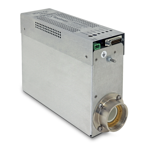
50-75W工業用X線発生器
MFXシリーズは、スペルマンの非常に優れた高電圧パッケー ジング、表面実装組み立て技術そして弊社独自のモールド技術を 結集させた超コンパクトOEM用X線発生装置モジュール す。
MFXシリーズはさまざまなメーカーのフローティング・フィ ラメント電源X線管に対応するために設計されています。0~ 50kV(または0~65kV)の電圧、2mAまでのエミッション電流 を50W, 65W, 75Wの制限内で出力できます。+24Vdc入力 で動作します。MFXは高くレギュレートされたビーム電流を供 給するために、閉ループ・フィラメント・ビーム制御回路を利用 しています。交流フローティング・フィラメント電源は、0.3A から4A間で動作します。MFXは厳しいレギュレーション、高安 定および低リップルを提供します。ビーム電圧、エミッション電 流およびフィラメント電 制限を設定するために、ローカル制御 とリモート・アナログ制御を備えています。更にオプションとし て、USB、RS-232もしくはEthernetインターフェースが利用 可能です。
Specifications
(Ref. 128101-001 REV. K)
J2 POWER INPUT CONNECTOR
| Pin | Signal | Parameters |
|---|---|---|
| 1 | +24V Input | +24 volts @ 5A, max. |
| 2 | 24V Return (Gnd.) | Power Ground |
J4 ANALOG INTERFACE CONNECTOR MALE 15 PIN MINI "D"
| Pin | Signal | Parameters |
|---|---|---|
| 1 | Monitor Return | Signal Ground |
| 2 | Voltage Monitor | 0-10 volts = 0 to full scale, Zout=1KΩ |
| 3 | Current Monitor | 0-10 volts = 0 to full scale, Zout=1KΩ |
| 4 | Interlock Output | Connect 12V HVON bulb to pin 15 to enable |
| 5 | +10 Volt Reference | +10 Volts @ 1mA, maximum |
| 6 | Filament Monitor | 1 volt = 1 amp, Zout=1KΩ |
| 7 | Voltage Program Input | 0-10 volts = 0 to full scale, Zin=10MΩ |
| 8 | Local Voltage Program* | 10 turn pot., screwdriver adjust |
| 9 | Filament Limit Setpoint* | 1 volt = 1 amp, screwdriver adjust |
| 10 | Current Program Input | 0-10 volts = 0 to full scale, Zin=10MΩ |
| 11 | Local Current Program* | 10 turn pot, screwdriver adjust |
| 12 | Not used (+24V Out for Interlock) | (Optional Interlock configuration) |
| 13 | Not used (Interlock Coil) | (Optional Interlock configuration) |
| 14 | Filament Preheat Setpoint* | 1 volt = 1 amp, screwdriver adjust |
| 15 | Interlock Return | Interlock Ground |
*Denotes 10 turn potentiometer located on front panel
J1 CATHODE OUTPUT CLAYMOUNT HV CONNECTOR
| Pin | Output Connection |
|---|---|
| C (common) | -High Voltage Output |
| S (small) | -High Voltage Output |
| L (large) | Filament Output |
| G (grid) | Filament Output |
Note: No high voltage cable is provided
Recommended Cable:
Claymount part number: 11470
Cable assembly, L3 CA11, CA11, 10F, CS=Bare 10 foot, Mini Federal Connectors on both ends, "C" and "S" are both connected to the bare wire
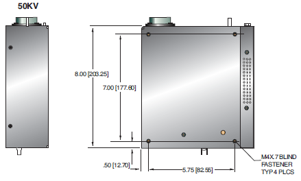
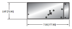
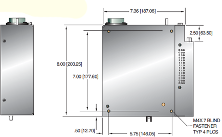
Tables & Diagrams
DIMENSIONS: in.[mm]
50KV
50KV WITH SIC OPTION
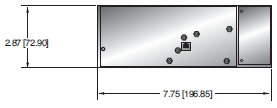
65KV
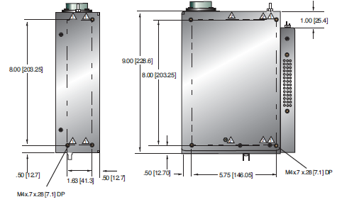
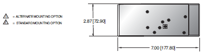
65KV WITH SIC OPTION

Frequently Asked Questions
Application Notes AN-12 – The Benefit of Using a Current Source to Power X-Ray Tube Filament Circuits
Application Notes AN-01 – Fundamentals of X-Ray Generator – X-Ray Tube Optimization

