SL2KW
- Very Compact and Lightweight
- Low EMI and RFI
- Voltage Range from 500V to 50kV
- Reversible Polarity Standard up to 8kV
- Optional VFD Front Panel/Ethernet Interface
- Extensive Analog and Digital Interface
- Arc Quench/Arc Count/Arc Trip
- OEM Customization Available
*Note: All specifications are subject to change without notice. Please consult the English PDF version of this datasheet for the most up-to-date revision.


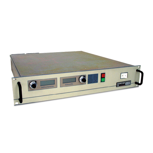
Compact 2kW High Voltage Power Supplies
Spellman’s SL2KW Series of 2kW high voltage power supplies are designed to meet uncompromising performance standards in a minimum of space. Their circuitry includes a resonant high frequency inverter with proprietary control which provides faultfree operation in extreme transient and arcing environments with greater than 85% efficiency. These full featured supplies are available in a wide range of outputs with many options.
Typical applications:
- Semiconductor Manufacturing
- Electrostatics
- EBeam Systems
- Capacitor Charging
- CPT/CRT Testing
- Hipot Testing
- General Laboratory
- CW Lasers
사양
(Ref. 128071-001 REV. R)
Status Indicators:
Voltage and Current Control Mode, Interlock Open and Closed, High Voltage Inhibit, Overcurrent and Overvoltage, Arc, Regulation Error, Overtemperature.
Input:
Standard: 208Vac ±10%, 50/60Hz @ 8.5A/phase, three phase
Optional: 220Vac ±10%, 50/60Hz @19.75A, single phase
Output:
Models available from 0.5kV to 50kV. Each model is available in positive, negative or reversible polarity output.
Front Panel Controls:
Voltage and current are continuously adjustable by tenturn potentiometers with lockable counting dials, ON/OFF circuit breaker/lamp, high voltage ON switch/indicator and high voltage OFF switch/indicator.
Voltage Regulation:
Load: 0.005% of maximum voltage +500mV for full load change. Line: ±0.005% of full voltage +500mV over specified input range
Current Regulation:
Load: 0.01% of maximum current ±100µA
for full voltage change.
Line: ±0.005% of maximum current for a ±10%
input line change.
Ripple:
0.1% pp +1Vrms, three phase line input
0.3% pp +1Vrms, single phase line input
Temperature Coefficient:
100ppm/°C voltage or current regulated. Higher
stability is available on special order.
Environmental:
Temperature Range:
Operating: 0°C to 50°C.
Storage: -40°C to 85°C.
Humidity:
10 to 90% relative humidity, noncondensing
Stability:
100ppm/hour after 1/2 hour warmup for
both voltage and current regulation.
Metering:
Digital voltage and current meters, 31/2
digit ±1 least significant digit.
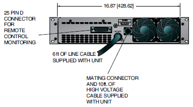
Interface Connector:
25 pin male D connector
Output Cable:
10’ (3.3m) of shielded high voltage
cable removable at the rear panel.
AC Line Input Cable:
A 6 foot (1.83m) cable is permanently attached to the unit. Single phase units use 3 conductor 12AWG cable, three phase units use 4 conductor 16AWG cable.
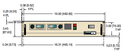
Dimensions:
31/2”H(2U) x 19”W x 19”D
(8.9cm x 48.3cm x 48.3cm).
Weight:
17 to 26lbs (7.7 to 11.8kg) depending on model.
Regulatory Approvals:
Compliant to EEC EMC Directive for 3 phase units, conducted and radiated emission only for single phase units. Compliant to EEC Low Voltage Directive. RoHS Compliant.
Electronic Component (Power Source)
SL2KW series is intended for installation as a component of a system. It is designed to meet CE standards, with conditions of acceptance often being: customer provided enclosure mounting, EMC filtering, and appropriate protection, and isolation devices. The SL2KW series is not intended to be operated by end users as a stand-alone device. The SL2KW series power supply can only be fully assessed when installed within a system, and as a component part within that system.
eSL Option
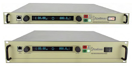
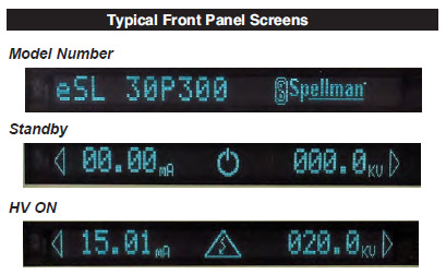
The eSL Option provides a vacuum fluorescent front panel display and Ethernet connectivity. Both the 1U (1.75”) and 2U (3.5”) SL product offerings are available with the eSL Option. Using the front panel local controls the main menu has the following features:
Local/Remote Control
Allows operation from either the local front panel or remotely via the Ethernet Category 5 connector.
Features Menu
Allows control over Adjustable Overload Trip and Slow Start features.
Tutorial Menu
Provides information on how to use the local front panel interface.
Diagnostics Menu
Provides information on the revisions of the hardware, firmware and IP address. Additionally the Diagnostics Menu provides information on the status of the internal low voltage housekeeping power supply voltages.
eSL Option power supplies can still be fully controlled via the SL2KW’s comprehensive remote analog interface, so these units are fully backwards compatible with standard SL2KW’s power supplies.
SL2KWSELECTIONTABLE
| Maximum Rating | Model Number | |
|---|---|---|
| kV | mA | |
| 0.5 | 4000 | SL0.5PN2000 |
| 1 | 2000 | SL1PN2000 |
| 2 | 1000 | SL2PN2000 |
| 3 | 666 | SL3PN2000 |
| 6 | 333 | SL6PN2000 |
| 8 | 250 | SL8PN2000 |
| 10 | 200 | SL10*2000 |
| 15 | 133 | SL15*2000 |
| 20 | 100 | SL20*2000 |
| 30 | 66.6 | SL30*2000 |
| 40 | 50 | SL40*2000 |
| 50 | 40 | SL50*2000 |
*Specify “P” for positive polarity or “N” for negative polarity or“PN” for reversible polarity
SL2KW 25 PIN D CONNECTOR
| TB1 | Signal | Signal Parameters |
|---|---|---|
| 1 | PowerSupply Common | Signal Ground |
| 2 | External Inhibit | Ground=Inhibit, Open=HV On |
| 3 | External Interlock | +15V at Open, <15mA at Closed |
| 4 | External Interlock Return | Return for Interlock |
| 5 | Current Monitor | 0 to 10V=0 to 100% Rated Output |
| 6 | kV Test Point | 0 to 10V=0 to 100% Rated Output |
| 7 | +10Vdc Reference | +10Vdc, 1mA Max |
| 8 | Remote Current Program In | 0 to 10V=0 to 100% Rated Output |
| 9 | Local Current Program Out | Front Panel Program Voltage |
| 10 | Remote Voltage Program In | 0 to 10V=0 to 100% Rated Output |
| 11 | Local Voltage Program Out | Front Panel Program Voltage |
| 12 | EFR Common | Optional: External Fault Relay 30V @ 2A Maximum |
| 13 | EFR-NC/EFR-NO | |
| 14 | Local HV Off Out | +15V at Open, <25mA at Closed 15 HV Off Connect to HV OFF for FP Operation |
| 15 | HV Off | |
| 16 | Remote HV On | +15V, 10mA Max=HV Off |
| 17 | Remote HV Off Indicator | 0=HV On, +15V, 10mA Max=HV Off |
| 18 | Remote HV On Indicator | 0=HV Off, +15V, 10mA Max=HV On |
| 19 | Remote Voltage Mode | Open Collector 35V Max, 10mA Max, On=Active |
| 20 | Remote Current Mode | |
| 21 | Remote Power Mode | |
| 22 | Remote PS Fault | 0=Fault, +15V, 0.1mA Max=No Fault |
| 23 | +15V Output | +15V, 100mA Max |
| 24 | Power Supply Common | Signal Ground |
| 25 | Shield Return | Chassis Ground |
| How to Order: |
|---|
|
Sample model number: SL20PN2000/NSS/DPM4 |
There may be some restrictions on multiple option combinations. Please contact our Sales department for more details.
SL2KW SERIES OPTIONS
AOL Adjustable Overload Trip
A control board jumper is moved to make the power supply shut down if it ever operates in current mode. This allows the user to set the current programming level as a trip point that will turn the power supply off with an Over Current fault if it ever tries to operate in Current Mode.
APT Adjustable Power Trip
A third control loop is installed in the power supply, a power loop. This power loop uses an analog multiplier chip to multiply the voltage and current feedback signals to create a power feedback
signal. Programming and feedback scaling is 0-10Vdc = 0-100% of rated power. The circuit is configured to trip the power supply off with an Over Power fault if the power loop ever tries to regulate.
ARC Arc Sense
A signal is provided on a spare pin (TB1-21) that changes state whenever the power supply detects an arc.
AT Arc Trip
A control board jumper is moved such that the first arc sensed will shut the power supply off with an ARC fault.
BPM Bipolar Master
BPS Bipolar Slave
This option configures two identical but opposite polarity units to function as a single tracking bipolar supply. The voltage feedback of the master (positive unit) is provided to the voltage
programming input of the slave (negative unit).
CMS Current Mode Select
A front panel switch is provided to allow the power supply to either regulate in current mode or create an over current fault when operated in current mode, which will shut down the supply. This is basically a switch selectable AOL option.
CPC Constant Power Control
Identical to the APT Option with the exception the power supply will run and regulate when the power loop becomes active.
DPM4 Digital Panel Meter, 4.5 digits
The standard 3.5 digit front panel meters are replaced with 4.5 digit panel meters.
EFR External Fault Relay
A set of relay contacts are provided via the rear panel interface that will change state if the power supply shuts down due to a fault condition.
eSL Ethernet Connectivity/VFD Front Panel
The eSL Option provides a vacuum fluorescent front panel display, Ethernet connectivity and comprehensive front panel controls.
FCV Fine Control Voltage
This option adds a second potentiometer to the front panel of the unit. This allows for a finer local adjustment of the output voltage setting.
IO Instant On
A jumper is placed between TB1-15 and TB1-16 on the rear panel, causing the power supply to automatically toggle into HV ON when ever the line voltage is applied. LL(X) Lead Length Extra long high voltage output cable. 20, 40, 60 and 100 feet are standard lengths. Non standard lengths can be custom ordered.
NAD No Arc Detect
This option removes the arc intervention circuitry from the power supply. Care must be exercised when using this option as damage to the HV multiplier could occur.
NSS No Slow Start
The standard 6 second long linear ramp of output voltage is removed allowing the high voltage to “step” to its set point when enabled.
PN Positive/Negative
Reversible polarity option. Units that are not inherently reversible by design (10kV to 50kV) can have their output polarity reversed by the process of exchanging the high voltage multiplier section.
RFR Remote Fault Reset
This option provides the ability to reset any power supply faults that might occur via toggling a signal on the rear panel interface.
ROV Remote Over Voltage
The programming signal for the over voltage comparator circuit is made available to the customer remotely, allowing the power supply to be set to trip the OVP circuit anywhere from 0 -110% of rated output voltage.
SL Slides
Industry standard rack mounted slides are installed on the power supply. SS(X) Slow Start(X) The standard slow start is modified to provide a
time of (X) seconds. Time frames of 0.1 seconds to 120 seconds can be accommodated.
SS(X) Slow Start(X)
The standard slow start is modified to provide a time of (X) seconds. Time frames of 0.1 seconds to 120 seconds can be accommodated.
There may be some restrictions on multiple option combinations. Please contact our Sales department for more details.
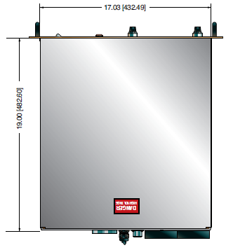
테이블 및 다이어그램
DIMENSIONS: in.[mm]
FRONT VIEW
TOP VIEW
BACK VIEW
Frequently Asked Questions
What Is a Safe Level of High Voltage?
What Is an “External Interlock”?
Where Can I Obtain Information on High Voltage Safety Practices?
Can I Operate a High Voltage Power Supply Designed for 220VAC, Single Phase From a 208VAC, Three Phase Electrical Service?
What Kind of High Voltage Connector Do You Use on Your Supplies?
What Do You Mean That the Output Side of the High Voltage Cable on Most Standard Products Is “Unterminated”?
How Should I Ground Your Supply?
Why Is Arcing an Issue for a High Voltage Power Supply?
Application Notes AN-13 – Arc Intervention Circuitry and External Series Limiting Resistors
Application Notes AN-14 – The Limits of Front Panel Digital Meters
Application Notes AN-15 – 3.5 And 4.5 Digit Meter Displays Explained
Application Notes AN-18 – Current Loop/Arc Detection Circuitry
Application Notes AN-19 – High Voltage Cable Lengths Discussed
Application Notes AN-23 – SL HV Off and HV on Circuitry Explained

