SPX Series
- Constant Potential Output
- Excellent Stability and Regulation
- Power Factor Corrected AC Input Circuitry
- Digital Interface, Ethernet and RS-232
- End Grounded Exposed Anode
- Portable, Repeatable, Accurate
- 100% Duty Cycle
- Unparalleled Resolution Imaging
- Liquid or Air Cooled Models
- Penetration of up to 76mm of Fe (300kV unit)
*Note: All specifications are subject to change without notice. Please consult the English PDF version of this datasheet for the most up-to-date revision.
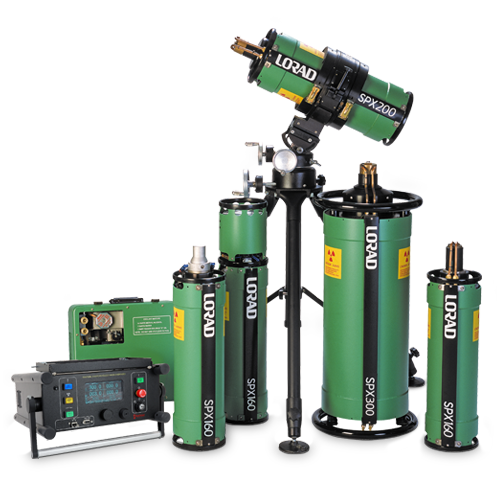
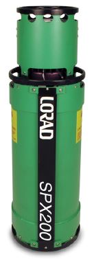
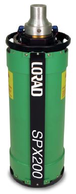
160kV, 200kV, 300kV Portable Industrial NDT X-Ray Imaging System
Spellman’s SPX Series are perfectly suited for today’s demanding NDT inspection requirements. SPX units are rugged, yet easy to transport and economical to maintain. They can be line or portable generator powered automatically adapting to standard input voltages to permit all day inspection under extreme conditions virtually anywhere.
The end grounded X-Ray tubes have a focal spot size of 1.5mm sq. and the exposed anode allows for easy and flexible positioning of the tube head assembly. Tube ports use a low-absorption beryllium window that allows the radiographer to utilize the full spectrum of X-Ray energy. The high radiation output of the SPX systems allow for lower kV per exposure, shorter exposure times and increased film contrast for superior radiographic imaging.
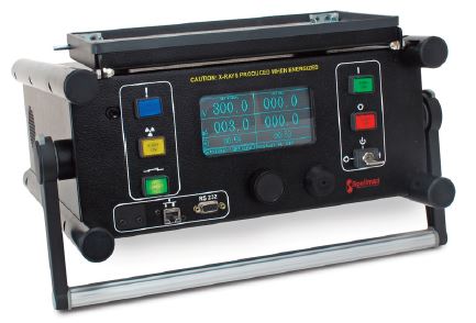
The SPX microprocessor-driven control unit provides automatic warm-up and comprehensive self-diagnostic circuitry. Memory to store and recall exposure techniques is standard and the last set of exposure parameters is retained before powering down. The SPX is adjustable in 1kV and 0.1mA increments. Exposure duration can be set from 1 second to 99 min 59 seconds in 1 second increments. There are three models to choose from: 160kV, 200kV and 300kV.
Typical Applications:
- Aerospace
- Manufacturing
- Defense
- Aviation
- Energy
- Security Systems
- NDT Applications
OPTIONAL ACCESSORIES
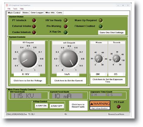
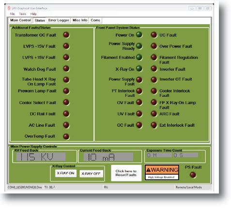
GUI Control Software for the SPXGUI is specifically designed for controlling SPX series systems. As an alternative to the front panel control, the GUI will allow the user to control all necessary functions of the system from a userfriendly windows based menu. Additionally the GUI can be used as a diagnostic tool when the system is controlled via the front panel.
- Automatic warm-up of the X-Ray tube
- Timed or Continuous Exposure modes
- Fault and status monitor
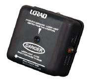
Laser Pointer
Spellman’s exclusive Laser Pointer allows pinpoint image area targeting. The Laser Pointer projects a highly visible reference laser beam from the tubehead to surfaces up to 75 feet away, showing precisely where the central X-Ray beam will be located, providing unmatched accuracy for greater efficiency and reduced set-up times.
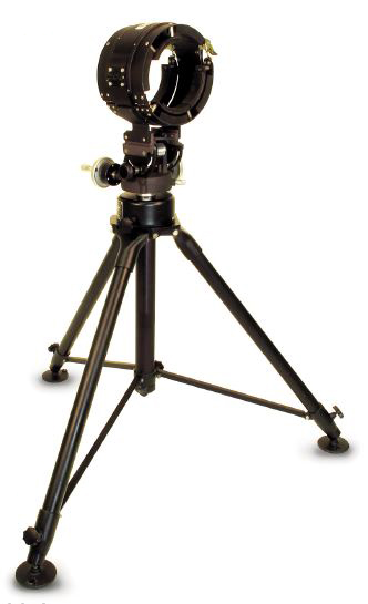
Tubehead Stand
An optional X-Ray Tubehead Stand allows for quick set up and provides rigid support for optimal image quality with three-axis positioning of the tube head assembly. The stand incorporates telescoping legs, a hand wheel-driven variable height adjustment and lockable hand wheel controlling the tubehead tilt and horizontal rotation. The tubehead cradle is cushioned for secure mounting and vibration damping. A bubble-type indicator is included for quick and easy leveling of the tubehead. Black anodized aluminum construction. 35lbs. (16kg) approx.
Air Cooled Tube Head Assembly
The air cooled tube head assembly uses a heat sink and high volume fan to dissipate heat from the anode and typically is used in applications that do not have limited access and are not in a volatile fuel vapor atmosphere. The air cooled tube head assembly does not require the cooler unit and the associated mixing and maintenance of liquid coolant. This unit requires less user maintenance and could be considered more environmentally friendly.
Panoramic Tube Head Assembly
The panoramic tube head assembly comes in a liquid cooled version only and produces radiation in a 360 degree cone making it ideal for aircraft FOD inspection, inspection of tanks or pipes or any application that requires circumferential radiographic inspection.
Specifications
(Ref. 128121-001 REV. K)
Input Line Requirements:
Automatically adapts to input line voltage
200-250Vac, 50/60Hz, 10 Amperes maximum
May also be portable-generator powered
X-Ray Output
SPX160: 20 to 160kV, 0.5mA to 5.0mA (800 watts max.)
SPX200: 10 to 200kV, 0.5mA to 10.0mA (900 watts max.)
SPX300: 10 to 300kV, 0.5mA to 10.0mA (900 watts max.)
Constant potential, end-grounded anode, air or liquid cooled versions available
X-Ray Tube Window:
SPX160: Beryllium 0.8mm (directional)
Nickel 0.6mm (panoramic)
SPX200: Beryllium 1.0mm
SPX300: Beryllium 1.0mm
Radiation Coverage:
SPX160: 40° directional or 360° panoramic tube available
SPX200: 40° directional or 360° panoramic tube available
SPX300: 40° x 60°
Radiation Output:
SPX160: 14R/min at 50cm filtered with 0.5 inches (12.7mm)
aluminum at 160kV, 5mA
SPX200: 21R/min at 50cm filtered with 0.5 inches (12.7mm)
aluminum at 200kV, 4.5mA
SPX300: 30R/min at 50cm filtered with 0.5 inches (12.7mm)
aluminum at 300kV, 3mA
Radiation Leakage:
Less than 2.0 Roentgens per hour at 1 meter from
the X-Ray tube target.
Effective Focal Spot:
SPX160:
Standard: 0.03 x 0.04 in. (0.7 x 1.0mm) EN12543
0.02 in. sq. (0.5mm sq.) IEC60336
Panoramic: This tube has a flat target (0 degree) and therefore it is without dimension along the tube axis (other than panoramic tubes with conical targets). The true focal spot on the target can only be estimated by taking two focal spot film exposures in the main beam 90 degrees apart from each other. Due to this no focal spot is inferred.
SPX200:
Standard: 3mm x 3mm (0.12in x 0.12in) EN12543
0.060 in. sq. (1.5mm sq.) IEC60336
Panoramic: 0.4mm x 4mm (0.016in x 0.16in) EN12543
SPX300:
Standard: 3mm x 3mm (0.12in x 0.12in) EN12543
Ambient Temp:
100% duty cycle @ 120°F (49°C)
Duty Cycle:
100% - liquid or air cooled
Storage Temp:
-30°F to 160°F (-35°C to 71°C)
Anode Cooling:
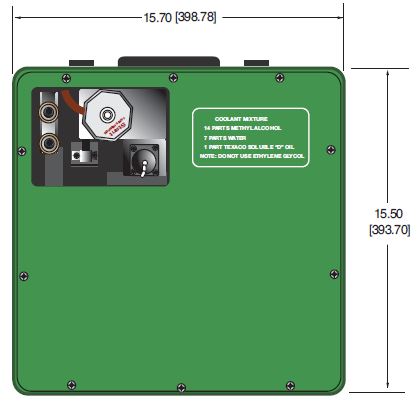
Liquid coolant solution closed loop between X-Ray tube anode and cooling unit, or fan forced air cooling.
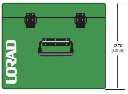
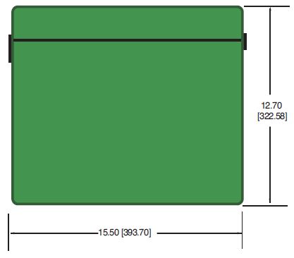
Liquid Cooling Unit Dimensions:
Please reference dimension drawings
Liquid Cooling Unit Weight:
54lbs. (15.4kg) approx.
Tube Head Dimensions:
Please reference dimension drawings
Tube Head Weight:
SPX160:
Liquid Cooled: 29lbs. (13.15kg)
Air Cooled: 33lbs. (14.97kg)
Panoramic: 29lbs. (13.15kg)
SPX200:
Liquid Cooled: 37lbs. (16.78kg)
Air Cooled: 41lbs. (18.60kg)
Panoramic: 37lbs. (16.78kg)
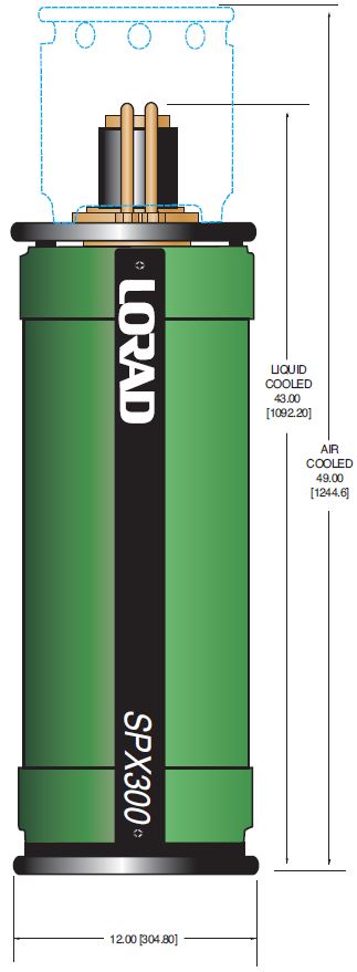
SPX300:
Liquid Cooled: 98lbs. (44.5kg)
Air Cooled: 105lbs. (47.61kg)
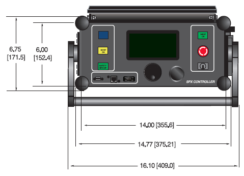
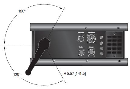
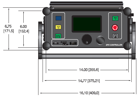
X-Ray Control Unit:
Digital microcomputer based with local control, RS-232 and Ethernet
X-Ray Control Unit Dimensions:
Please reference dimension drawings
X-Ray Control Unit Weight:
26lbs. (11.8kg) approx.
Safety Devices:
- Tubehead Pressure Relief Valve
- Tubehead Thermal Cut-Out
- Tubehead Pressure Gauge
- Tubehead Low Pressure Cut-Out @ 25psi (1.72 Bar)
- Coolant Flow Sensor (liquid cooled only)
- Control Unit Safety Keyswitch
- Microcomputer-based Self Diagnostics
- Continuous Exposure Parameter Display
Standard Accessories:
- Operation manual
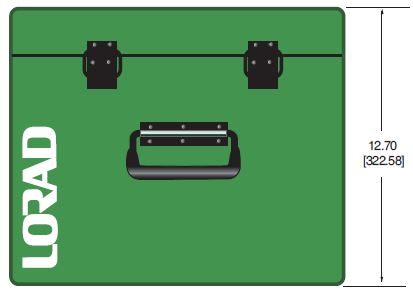
- Tubehead carrying case
- Tubehead Pressure Gauge
- Tubehead Cable- 100’ with strain relief
- Extra key (1) for Control Unit Safety Lock
- Power cable - 25’ with strain relief
- Coolant hose - twin, 50’ with self-sealing terminations (liquid cooled only)
- Cooler power cable
SPX160 MODEL SELECTION TABLE
| Model Number | Description |
|---|---|
| SPX160ACDBG | Air Cooled, 40° Directional Beam, Glass insert |
| SPX160LCDBG | Liquid Cooled, 40° Directional Beam, Glass insert |
| SPX160LCPANG | Liquid Cooled, PANoramic Beam, Glass insert |
SPX200 MODEL SELECTION TABLE
| Model Number | Description |
|---|---|
| SPX200ACDBC | Air Cooled, 40° Directional Beam, metal Ceramic insert |
| SPX200CPANC | Liquid Cooled, PANoramic beam, metal Ceramic insert |
| SPX200LCDBC | Liquid Cooled, 40° Directional Beam, metal Ceramic insert |
SPX300 MODEL SELECTION TABLE
| Model Number | Description |
|---|---|
| SPX300LCDBC | Liquid Cooled, 40° Directional Beam, metal Ceramic insert |
| SPX300ACDBC | Air Cooled, 40° Directional Beam, metal Ceramic insert |
SPX OPTIONS
| Model Number | Description |
|---|---|
| 3-000-0754 | SPX160/200 tubehead stand |
| 3-000-0756 | SPX300 tubehead stand |
| 3-000-0792 | Laser pointer for liquid cooled tube |
| K935 | SPX160 Laser pointer for air cooled tube |
| K936 | SPX200/300 Laser pointer for air cooled tube |
| K937 | SPX200 Laser pointer for liquid cooled tube |
| K938 | SPX300 Laser pointer for liquid cooled tube |
SPX MAIN AC INPUT
Controller Side; Male, 3 pins MS type
| PIN | SIGNAL |
|---|---|
| A | LINE 1 120/220Vac |
| B | LINE 2 Neutral 120/220Vac |
| C | Ground |
SPX INTERLOCK CONNECTOR
Controller Side; Female, 8 pins MS type
Tube Side; Male, 8 pins MS type
| PIN | SIGNAL |
|---|---|
| A | External Interlock |
| B | External Interlock |
| C | X-Ray ON External Light |
| D | External Lights Returns (GND) |
| E | Pre-Warning External Light |
| F | External Light Confirm |
| G | 24Vac Outut, 1A max. |
| H | H 24Vdc Return (com.) |
SPX FAN CONNECTOR (A/C ONLY)
Controller Side; Female, 8 pins MS type
Tube Side; Male, 4 pins MS type
| PIN (Control) | PIN (Tube Head) | SIGNAL |
|---|---|---|
| D | A | Fan 120Vac Line1 |
| C | B | Fan 120Vac Tap |
| G | C | Fan 120Vac Line2/Neutral |
| B | D | Ground |
| E | N/C | |
| F | N/C | |
| A | Flow Interlock | |
| H | Flow Interlock |
SPX INTERLOCK CONNECTOR (W/C ONLY)
Controller Side; Female, 8 pins MS type
Tube Side; Male, 8 pins MS type
| PIN | SIGNAL |
|---|---|
| A | Flow Interlock |
| B | Ground |
| C | 120/220Vac Line1 for Motor |
| D | 120/220Vac Line2/Neutral for Motor |
| E | 120Vac Motor Tap |
| F | 120/220Vac Motor Tap |
| G | 220Vac Motor Tap |
| H | Flow Interlock |
SPX160 TUBE HEAD CONNECTOR
Controller Side; Female, 10 pins MS type
Tube Side; Male, 10 pins MS type
| PIN | SIGNAL |
|---|---|
| A | Interlock Temperature /pressure |
| B | Ground |
| C | Ground |
| D | HV Transformer |
| E | mA Feedback |
| F | Filament Transformer |
| G | kV Feedback |
| H | kV Feedback Return (GND) |
| I | Filament Transformer |
| J | HV Transformer |
SPX200/300 TUBE HEAD CONNECTOR
Controller Side; Female, 14 pins MS type
Tube Side; Male, 14 pins MS type
| PIN | SIGNAL |
|---|---|
| A | Interlock Temperature/Pressure SPX200, N/C SPX300 |
| B | Ground |
| C | Ground |
| D | HV Transformer |
| E | mA Feedback |
| F | Filament Transformer |
| G | kV Feedback |
| H | kV Feedback Return (GND) |
| I | Filament Transformer |
| J | HV Transformer |
| K | N/C |
| L | Interlock Temperature/Pressure SPX300, N/C SPX200 |
| M | N/C |
| N | N/C |
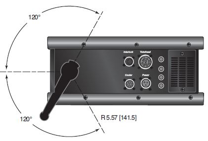
Tables & Diagrams
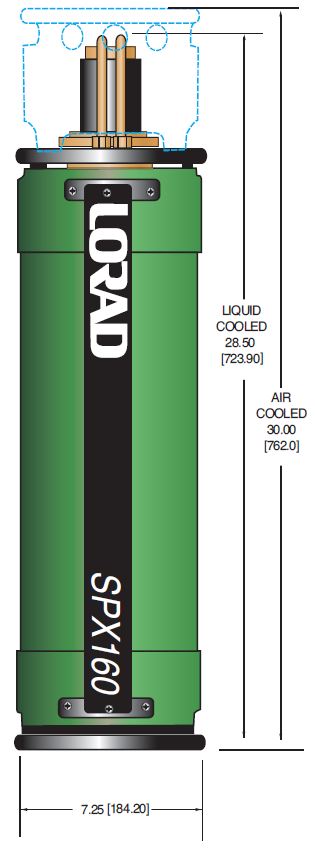
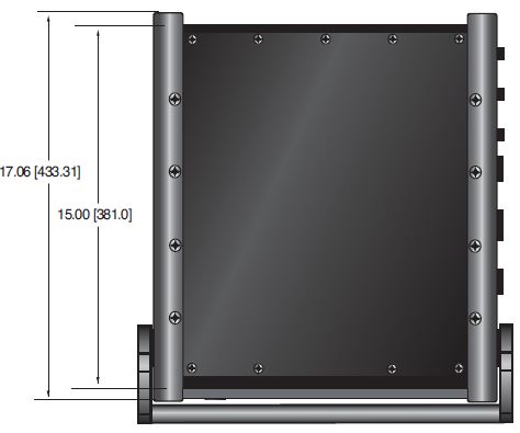
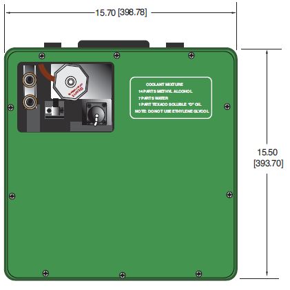
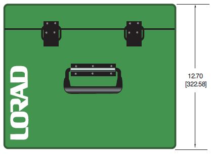
SPX160
DIMENSIONS: in.[mm]
CONTROL UNIT TOP VIEW
COOLER TOP VIEW
FRONT VIEW
FRONT VIEW
SIDE VIEW
SIDE VIEW
SPX160 TUBE HEAD SIDE VIEW
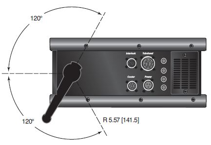
SPX200
DIMENSIONS: in.[mm]
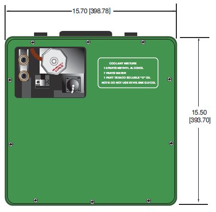
CONTROL UNIT TOP VIEW
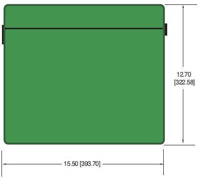
COOLER TOP VIEW
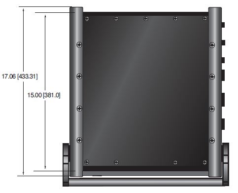
FRONT VIEW

FRONT VIEW
SIDE VIEW
SIDE VIEW
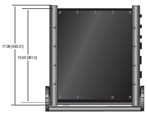
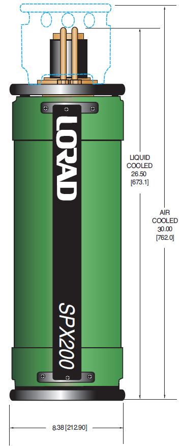
SPX200 TUBE HEAD SIDE VIEW
SPX300
DIMENSIONS: in.[mm]
CONTROL UNIT TOP VIEW
COOLER TOP VIEW
FRONT VIEW
FRONT VIEW
SIDE VIEW
SIDE VIEW

SPX300 TUBE HEAD SIDE VIEW