MMB125PN3.5 Medical MONOBLOCK®
- Integrated HV Supply, Filament Supply, X-Ray Tube, Beam Port and Control Electronics
- Compact & Lightweight
- <1ms Rise Time is Ideal for Extremities
- Specifically designed for the C-Arm OEM
*Note: All specifications are subject to change without notice. Please consult the English PDF version of this datasheet for the most up-to-date revision.

MMB125PN3.5 Medical MONOBLOCK®
Spellman’s MMB125PN3.5 Medical Monoblock® with <1ms rise time is ideal for extremities, specialized applications and vascular imaging. Benefit from Spellman’s 70 plus years of high voltage innovation with this MMB125PN3.5 Monoblock® X-Ray source specifically designed for the C-Arm OEM. Our advanced technology and design expertise in conjunction with our depth of manufacturing capabilities position Spellman as the wise choice for your Monoblock® requirements.
Spellman’s Ultra-Fast MMB Series utilizes our unique technologies that increases the quality of the X-Ray beam and significantly reduces patient dose. Pulsed Fluoroscopy enhances imaging of dense and complex anatomy to further support dose management. With a rise time of <1ms, Spellman’s MMB Series is among the fastest in the industry.
Specifications
(Ref. 128143-001 REV. A)
SPECIFICATIONS
X-Ray Characteristics:
Focal Spot: 0.5mm for small focus
1.6mm for large focus
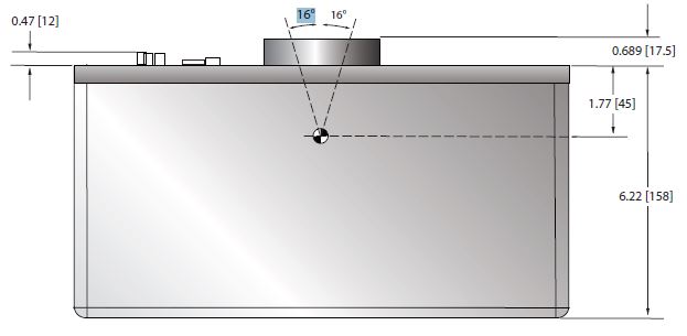
Target Angle: 16°
Target Material: Tungsten
Beam Filter: 0.8mm Al
Beam Geometry: Refer to line drawing
X-Ray Leakage: Less than <1mGy/hour @ 1meter
from tank surface.
Maximum Filament Current: 4.3A
Filament Inverter
Switching Frequency: 20kHz
Anode Heat Content: 35.5kJ
Maximum Anode
Heat Dissipation: 600W
Distance Between
Focal Spot to X-Ray
Output Window: 45mm
Focal Spot Position: Refer to outline drawing, additionally
it is marked on tank cover.
Input Power:
Input Voltage: 190-264Vac, single phase, 50/60 Hz
Continuous Current: ≤9A @ 600W, 220V
Peak Current: ≤34A @ 3500W, 220V
X-Ray Tube Voltage:
Operational Range: 40 to 125kV
kV Rise Time: <1ms (from 10% to 90%)
Reproducibility: ≤0.05 per IEC60601-2-54
kV Ripple: ≤1%
kV Accuracy
Fluoroscopy: ±5%
kV Overshoot: ≤5%
X-Ray Tube Current:
Fluoro: 0.2mA to 6 mA (small focal spot)
Pulsed Fluoro: 0.5mA to 10 mA (small focal spot)
Radiography: 10mA to 40mA (large focal spot)
mA Accuracy: ±10%
Maximum Operating Conditions:
Continuous
Low Level Fluoro: 6 mA for 5 minutes
Continuous
High Level Fluoro: 10 mA for 2 minutes
Pulsed Fluoro: 0.5fps, 1fps, 2fps, 4fps, 8fps, 15fps,
25fps, 30fps for 2 minutes
Pulse on time: the lower value of 40ms
or 50% duty cycle
Radiographic: Single shot large focal spot,
0.1 seconds @ 3500 watts
Maximum Anode
Heat Dissipation: 600W
Average Power: 600W for 5 minutes
Tank Heat Content: No less than 675kHU
Max. Cooling Rate: 150W
X-Ray Tube Current Protection:
Over Current (High mA): Trip point is set at 15% over maximum rated current, or at 15% over programmed output current value for longer than 50ms.
Under Current (High mA): Trip point is set at 15% under programmed output current value for longer than 50ms.
Over Current (Low mA): Trip point is set at 20% over maximum rated current, or at 20% over programmed output current value for longer than 50ms.
Under Current (Low mA): Trip point is set at 20% under programmed output current value for longer than 50ms.
X-Ray Tube Voltage Protection:
Over Voltage (High kV): Trip point is when the kV output exceeds 137.5kV for more than 10ms or it set is at 10% over programmed output voltage value for longer than 30ms.
Under Voltage (Low kV): Trip point is set at 10% under the programmed output voltage value for longer than 30ms.
X-Ray Tube Arc Protection:
Arc Intervention: Unit will detect an Arc but HV will not be shut down, but if multiple arcs occur (4 arcs in 10 seconds) the unit will shut down.
Over Temperature Protection:
Over Temperature: Over temperature of tank cover trip point shall be within 60°C ±5°C. Over temperature of tank oil trip point shall be set 65°C.
Operating Temperature: 0 to +40 ºC.
Storage Temperature: -20 to +70 ºC
Altitude: 0 to 8000 feet (0 to 2438 meters)
Humidity: 5 to 95%, non-condensing.
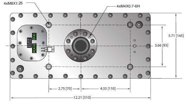
Dimensions: X-Ray Tank: 12.2” x 6.2” x 5.7” (310mm x 158mm x 145mm)
Refer to outline drawing.
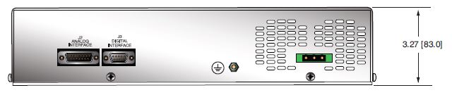
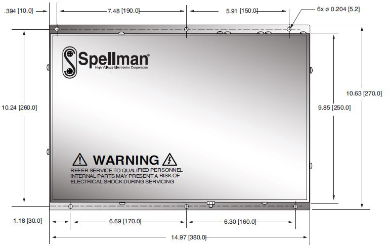
Controller: 14.9” x 10.6” x 3.2” (380mm x 270mm x 83mm) Refer to outline drawing.
Weight:
X-Ray Tank: 27.5 pounds (13kg)
Controller: 9.9 pounds (4.5kg)
Regulatory Approvals:
Designed to be compliant to:
IEC 60601-1:2005+A
Medical electrical equipment Part 1: General requirements for basic safety and essential performance.
IEC 60601-1-2
2007 Medical electrical equipment Part 1-2: General requirements for basic safety and essential performance- Collateral standard: Electromagnetic compatibility—Requirements and tests.
IEC 60601-1-3
2008 Medical electrical equipment Part 1-3: General requirements for basic safety and essential performance- Collateral standard: Radiation protection in diagnostic X-Ray equipment.
IEC 60601-2-54
2009 Medical electrical equipment Part 2: Particular requirements for the basic safety and essential performance of X-Ray equipment for radiography and radioscopy.
EMC
Designed to meet IEC requirements for medical components. (Note: External EMI filter may be required)
RoHS
Controller and Tank Assembly are RoHS compliant.
AC LINE POWER CONNECTOR— TE: 1-350943-0
| PIN | SIGNAL | PARAMETERS |
|---|---|---|
| 1 | Ground | Earth Ground |
| 2 | AC Input 1 | 190 - 264Vac, single phase, 50/60Hz, 34A max. |
| 3 | AC Input 2 | 190 - 264Vac, single phase, 50/60Hz, 34A max. |
DIGITAL INTERFACE—9 PIN FEMALE D CONNECTOR TE: 5747844-5
| Pin | Signal | Parameters |
|---|---|---|
| 1 | N/C | No Connection |
| 2 | RS-232 TX Out | RS-232 Transmit |
| 3 | RS-232 RX In | RS-232 Receive |
| 4 | NC | No Connection |
| 5 | RS-232 Ground | Ground from RS-232 transceiver IC |
| 6 | NC | No Connection |
| 7 | NC | No Connection |
| 8 | NC | No Connection |
| 9 | NC | No Connection |
ANALOG INTERFACE—15 PIN FEMALE D CONNECTOR TE: 5747845-5
| PIN | SIGNAL | PARAMETERS |
|---|---|---|
| 1 | GND | Signal Ground |
| 2 | +5Vdc Out | +5Vdc, 100mA max. |
| 3 | Prep | User signal (Contact Closure) to alert the generator that exposure sequence will begin. Once this signal is active, exposure parameters are locked in and cannot be changed. Contact connection to pin 14. Closed = PREP, the filament is placed in preheat mode |
| 4 | Ready | The generator is ready for X-Ray exposure. Open Collector. Low/Active = Ready |
| 5 | Exposure | User signal (Contact Closure) to generator to generate X-Rays. Filament is boosted, and high voltage is generated after the boost time. Contact connection to pin 14. Closed = Exposure |
| 6 | X-Ray ON 75% Status | Transistor output to indicate X-Ray ON status synchronized with 75% of kV set point |
| 7 | X-Ray ON Status |
Transistor output to indicate X-Ray ON status synchronized with kV start up |
| 8 | X-Ray ON Shutdown |
User signal to generator to rapidly turn HV OFF and ON during serial exposure sequence. Low/Active=HV OFF |
| 9 | HVG Fault Status | Generator signal indicating generator fault. Open collector transistor output. Low/Active = Fault |
| 10 | kV Monitor | Signal from generator. 0-10V = 0-140kV |
| 11 | mA Monitor | Signal from generator. Large focus: 0-10V = 0-50mA Small focus: 0-5V=0-10mA |
| 12 | Filament Current Monitor | Signal from generator. 0-10V = 0-6A |
| 13 | Monitor Ground | Ground for reference of monitor signals |
| 14 | +24dc Out | For connection to PREP and EXPOSURE control relay coils |
| 15 | Shield Ground | For connection of interface cable shield to generator chassis ground |
Tables & Diagrams
DIMENSIONS: in.[mm]
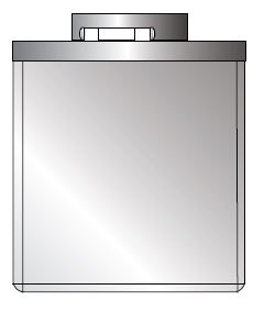
GENERATOR TANK
FRONT VIEW
TOP VIEW
CONTROL UNIT
FRONT VIEW
TOP VIEW
SIDE VIEW