Application Notes - High Voltage Power Supplies
SL HV OFF and HV ON Circuitry Explained
AN-23
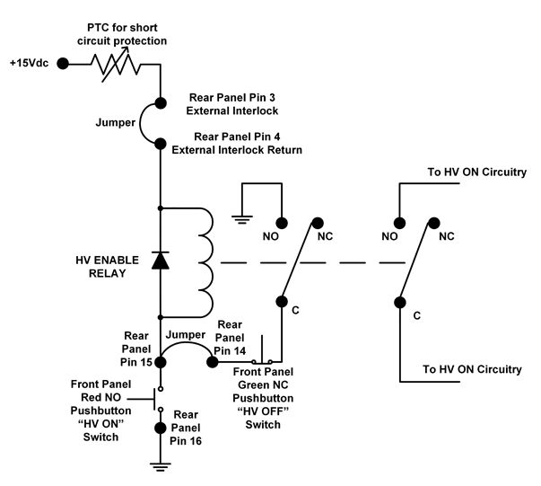
The above diagram shows a simplified SL HV ON/OFF schematic, functionally it is correct but it does not show all the actual circuitry. In reality, there are additional interlocks and circuitry that can turn off the high voltage if a fault is detected. The switches shown are the front panel HV OFF and HV ON switches. The three points on the simplified schematic are brought to the rear panel and are identified as pin 14, pin 15 and pin 16:

Pin 14: One side of the normally closed front panel HV OFF push button switch
Pin 15: The common point between the front panel HV OFF and HV ON push button switch
Pin 16: One side of the normally closed front panel HV OFF push button switch
HV OFF
Pins 14 and 15 are normally closed. They must be connected together to use the green front panel HV OFF switch, we ship the unit with a jumper in place. If you want to use a remote HV OFF switch, remove the jumper and connect a normally closed switch between these two points. If you open the remote switch (or press the front panel HV OFF switch), the unit will turn the high voltage off. Any remote HV OFF switch is placed in series with the front panel HV OFF switch.
HV ON
Pins 15 and 16 are normally open. When you momentarily press the red front panel HV ON switch you toggle and latch the high voltage on (assuming the interlock is closed and there are no faults present). If you want to use a remote HV ON switch, connect a normally open switch across pins 15 and 16. A momentary contact closure will turn the high voltage on. Any remote HV ON switch is placed in parallel with the front panel HV ON switch.
Spellman has used this high voltage ON/OFF circuitry on many of our rack mounted high voltage power supplies for decades, with outstanding results.


