
Application Notes - High Voltage Power Supplies
How do I change the polarity of the power supply?
AN-08
Most high voltage power supplies use a circuit called a voltage multiplier to create the desired high voltage output. This basic multiplier circuit is shown below in the simplified power supply block diagram:
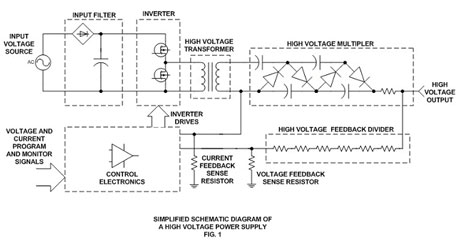
The multiplier circuit is comprised of an arrangement of capacitors and diodes. The orientation of the diodes will determine the output polarity of the unit. In the example above, the diodes shown would create a positive output polarity with respect to ground. If each diode was reversed in orientation, the multiplier would generate a negative output voltage with respect to ground.
The example above only shows a two stage, half-wave multiplier; using a total of four diodes. Full-wave multiplier stages are more efficient and use additional capacitors and twice as many diodes. To generate the high voltages typical of a Spellman supply, many multiplier stages are connected in series. If a twelve stage, full wave multiplier was made, a total of 48 diodes would be required.
Typically the capacitors and diodes used to fabricate a multiplier assembly are soldered directly to a single or sometimes several printed circuit boards. Frequently this assembly is encapsulated for high voltage isolation purposes.
To simplify the process of reversing the polarity (like in the instance of the SL Series) a second "opposite polarity" multiplier is provided above 8kV when reversibility is required. Exchanging the multiplier is a simple task needing only a screwdriver and few minutes of time. Modular style units due to their simplified designs, are typically not capable of having their polarity changed in the field.

