MPD Series
- Extremely Compact 10W High Performance Module
- Multiple Control Interfaces: Differential Analog, RS-232 and RS-485
- Voltage and Current Monitors
- High Stability, Low TC
- Ultra Low Ripple and Noise, Down to 1/f Band
- Free GUI for Testing and Development Work
- Digital Control Features: Multiple Units Operation, Current Control, Status Flags and Wobbler Function
*Note: All specifications are subject to change without notice. Please consult the English PDF version of this datasheet for the most up-to-date revision.


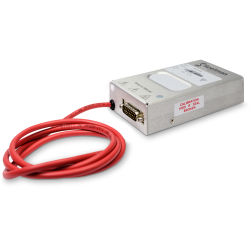
Spellman MPD Series of High Voltage 10 Watt Modules
Spellman’s MPD series is a family of high voltage, high performance 10 Watt modules with output voltages ranging from 1kV to 30kV.
Spellman’s hybrid topology of linear and switch mode power conversion techniques delivers ultra-low noise, excellent ripple and stability performance all within its compact footprint.
The MPD series can be controlled via analog or digital interfaces, both provided via a standard 15-pin D-type connector.
In analog mode, the unit features a differential amplifier input for the voltage programming signal to improve immunity from external system noise and address any offset issues. In digital mode, RS-232 and RS-485 interfaces provide additional features: current control, status flags, multiple units operation (RS-485 only), and wobbler function.
Spellman’s proprietary HV technology coupled with SMT circuitry results in an ultra-compact and lightweight module, available as either a positive or negative supply, that is ideal for OEM applications.
Typical Applications
- Mass Spectrometry
- Electrostatic Lenses
- Automatic test equipment
- Capillary Electrophoresis
- Electron and Ion Beams
- Microchannel Plate Detectors
- Electrostatic Printing
- Scintillators
- Electron Multipliers
- Electrospinning
- Electrostatic Chucks
- Photomultiplier Tubes
사양
(Ref. 128142-001 REV. F)
SPECIFICATIONS
Input Voltage:
+24 Vdc, ±2Vdc
Input Current:
≤1 amp maximum
Output Voltage:
7 models available from 1kV to 30kV
Output Polarity:
Positive or negative, specify at time of order
Power:
10 watts, maximum
Voltage Regulation:
Line: For a 1V line change 10ppm
Load: 0-100% load 10ppm
Current Limit:
110% of rated output current. In digital control mode, the current limit is settable from 0 to 110% of the rated output current.
Ripple:
See “drift, ripple and noise” table
Stability:
After one hour warm up period.
10ppm/hour
25ppm/8 hours
100ppm/1000 hours
Temperature Coefficient:
10ppm per degree C
Protection:
Arc and short circuit protected. Not designed to withstand continuous arcing. The unit monitors and reports faults through status flags (digital com). When a trip occurs, the output is disabled and the unit can be reset through enable, fault reset or power cycle.
Control Software:
A free GUI can be provided for customer testing and development work.
Main Features:
-Voltage control and enable inputs
-Voltage and current monitor outputs
-10V voltage reference output
Digital Features:
The following features are available when operating in digital control mode.
-Multiple units operation (RS-485 only)
-Current control
-Wobbler function: sine wave superimposed to voltage output (programmable amplitude 0-300V, period 0.1 to 2s)
Evironmental:
Operating: 0˚C to 50˚C
Storage: -35˚C to 85˚C
Environmental:
Temperature Range:
Operating: 0˚C to 50˚C
Storage: -35˚C to 85˚C
Humidity:
20% to 85% RH, non-condensing
Cooling:
Convection cooled
Dimensions:
1kV-10kV: 1.18˝ H X 2.75˝ W X 5.12˝ D (30mm x 70mm x 130mm)
15kV-20kV: 1.18˝ H X 2.75˝ W X 6.50˝ D (30mm x 70mm x 165mm)
30kV-20kV: 1.38˝ H X 2.95˝ W X 8.46˝ D (35mm x 75mm x 215mm)
Weight:
1kV-10kV: 14.82 oz. (420g)
15kV-20kV: 22.93 oz. (650g)
30kV: 33.51 oz. (950g)
Interface Connector:
15 pin male D connector
Output Connector:
Captive 39.4˝ (1 meter) long un-terminated and shielded HV cable:
1kV to 20kV units: HRG58
30kV units: LEMO 130666
Regulatory Approvals:
Compliant to EEC Low Voltage Directive. UK Conformity Assessed. UL/CUL recognized, File E354595. RoHS Compliant.
Note: for 1kV and 30kV units approvals, please inquire.
MPD SELECTION TABLE
| Model | Output Voltage | Output Current |
|---|---|---|
| MPD1*10/24 | 1kV | 10mA |
| MPD2.5*10/24 | 2.5kV | 4.00 mA |
| MPD5*10/24 | 5kV | 2mA |
| MPD10*10/24 | 10kV | 1mA |
| MPD15*10/24 | 15kV | 0.66mA |
| MPD20*10/24 | 20kV | 0.5mA |
| MPD30*10/24 | 30kV | 0.33mA |
*Specify “P” for positive polarity or “N” for negative polarity. Custom units available.
MPD DRIFT, RIPPLE and NOISE
| Model | 3mHz-30mHz | 30mHz-3Hz | 3Hz-30Hz | 30Hz-300Hz | 300Hz-30kHz | 30kHz-3MHz |
|---|---|---|---|---|---|---|
| MPD1 | 7mV | 7mV | 7mV | 4mV | 4mV | 4mV |
| MPD2.5 | 10mV | 10mV |
10mV | 5mV | 5mV | 5mV |
| MPD5 | 10mV | 10mV | 10mV | 10mV | 10mV | 10mV |
| MPD10 | 20mV | 20mV | 20mV | 20mV | 20mV | 20mV |
| MPD15 | 30mV | 30mV | 30mV | 30mV | 30mV | 30mV |
| MPD20 | 40mV | 40mV | 40mV | 40mV | 40mV | 40mV |
| MPD30 | 60mV | 60mV | 60mV | 60mV | 60mV | 60mV |
MPD EXTERNAL INTERFACE—15 PIN MALE D CONNECTOR
| Pin | Signal | Parameters |
|---|---|---|
| 1 | Power Ground | Ground |
| 2 | +24Vdc Input | +24Vdc @ 1 amp maximum |
| 3 | Voltage Monitor Output | Voltage monitor 0-10Vdc for 0 to full scale output ±1% (wrt signal ground) Zout=10kΩ |
| 4 | Voltage Reference Output | 10Vdc @ 10mA maximum |
| 5 | Voltage Program Input | 0 to 10Vdc=0 to 100% rated output ±1%, Zin=10MΩ |
| 6 | Voltage Program Differential Amplifier Output |
0 to 10Vdc=0 to 100% rated output, Zout =10kΩ |
| 7 | Voltage Program Differential Amplifier Input—Positive |
0 to 10Vdc differential between pin 7 and pin 9 = 0 to 100% of rated output, diode clamped to ground, Zin =38kΩ |
| 8 | Current Monitor Output | Voltage monitor 0 to 10Vdc for 0 to full scale output ±1% (wrt signal ground) Zout=10kΩ |
| 9 | Voltage Program Differential Amplifier Input—Negative |
0 to 10Vdc differential between pin 7 and pin 9 = 0 to 100% of rated output, diode clamped to ground, Zin =38kΩ |
| 10 | Voltage Program Digital Output |
0 to 10Vdc = 0 to 100% rated output, Zout =10kΩ |
| 11 | Analog Signal Ground | Signal ground for control and monitoring |
| 12 | Enable Input | Low = Enable, TTL, CMOS, open collector compliant |
| 13 | Digital Mode | RS-232 or RS-485 configuration Low = RS-485, Open circuit = RS-232 |
| 14 | RS-232 TxD/RS-485 (-) | Transmit data (output) wrt pin 1 or RS-485 inverting |
| 15 | RS-232 RxD/RS-485 (+) | Receive data (input) wrt pin 1 or RS-485 non inverting |
Digital Control – Connect pin 5 to pin 10
Analog Control – Connect pin 5 to pin 6
테이블 및 다이어그램
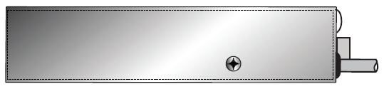
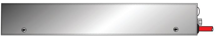
DIMENSIONS: in.[mm]
1kV-20kV
FRONT VIEW
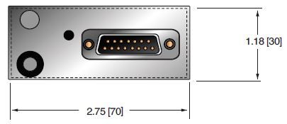
BOTTOM VIEW
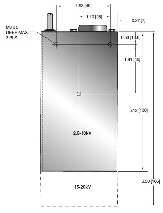
SIDE VIEW
30kV
FRONT VIEW
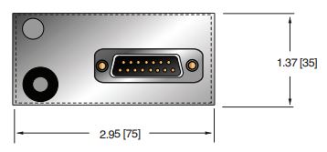
BOTTOM VIEW
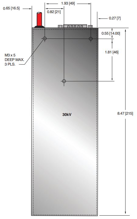
SIDE VIEW
Frequently Asked Questions
What Is a Safe Level of High Voltage?
Where Can I Obtain Information on High Voltage Safety Practices?
What Kind of High Voltage Connector Do You Use on Your Supplies?
What Do You Mean That the Output Side of the High Voltage Cable on Most Standard Products Is “Unterminated”?
How Should I Ground Your Supply?
Why Is Arcing an Issue for a High Voltage Power Supply?

