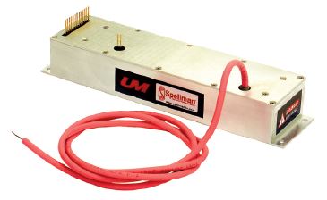
UM8-40シリーズ
- 8kV~40kVの9種類の電圧範囲、固定の負極性または正極性
- 4、15、30ワットの出力電力が可能
- 自動クロスオーバー制御による電圧/電流調整
- 電圧および電流モニター信号
- 完全なアークおよび短絡保護
- 高精度+5V基準出力
- 包括的な標準インターフェース
- CE認証、RoHS対応
*注: すべての仕様は予告なく変更される場合があります。最新版についてはこのデータシートの英語PDFをご覧ください。

![]()

DC-DC 高電圧電源
フォーム、フィット、ファンクションを考えた設計
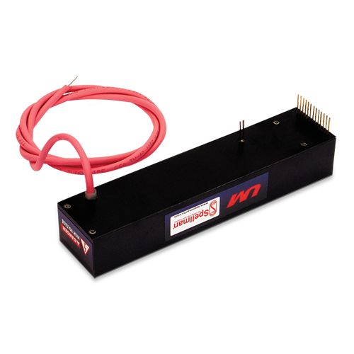
スペルマンのUMシリーズ、プリント回路基板マウント型高圧 モジュールは、一部の他社製品と取り付け・形状が同等であるた め容易な置き換えが可能です。 た、低価格で他にはない付加的 機能と利便性を提供します。この表面実装(SMT)ベースの高圧 モジュールは、独自開発の電力変換技術とスペルマンの60年に わたる高圧電源開発経験を かし、性能・信頼性の向上はもとよ り、他社製品に比べて低価格で、しかもシステムへの統合がこれ までより簡単です。
先進的な電力変換トポロジ
UMコンバータは当社独自開発のゼロ電圧スイッチング電力変 換トポロジを駆使し、これまでにない効率を提供する一方で、そ れに伴うノイズおよびリップル出力を低減します。従来のスイッ チングトポロジに比べて放射ノイズが少ないため、隣接する電気 回路から遮蔽する必要がほとんどなく、場合によっては全く必要 ありません。
高圧出力はフェライトコア高圧ステップアップ変圧器を使って 発生し、半波長コッククロフト・ウォルトン電圧マルチプライ ヤーへ送られ、指定の高圧出力が得られます。
高周波電力変換のスイッチング速度が固定されているため、出 力キャパシタンスが小さく、結果として蓄積エネルギーが最小限 に抑えられます。定格出力を抑えたサージ保護用抵抗と高速作動 電流ループを使うことで、アーク放電および短絡から完全に保護 します。
制御とレギュレーション
実際に発生する出力電圧は高インピーダンスのデバイダで抽出 され、電圧フィードバック信号が生成されます。電流フィードバッ ク信号は、電圧センス抵抗を介して高圧出力回路の低圧端側の帰 路に生成されます。この2つの正確なグランドリファレンス 力 電圧フィードバック信号は、装置の正確なレギュレートおよび制 御に使われるほか、外部モニタリングにも使われます。
UMの特異な変換トポロジにより、低インピーダンス負荷また は短絡回路の場合も全電流を印加することが可能です。標準装置 は最大定格出力の103%に制限されます。
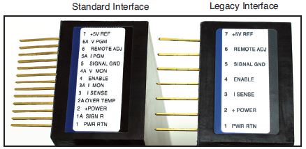
標準インターフェース
スペルマンのUMシリーズのインターフェースは電流プログラ ミング能力を備え、正極性、バッファ付き、低出力インピーダン スの電圧および電流モニター信号を生成します(0~+4.64 Vdc は0~定格全出力に相当します)。電圧プログラミング信号は0~ +4.64 Vdcが0~100%定格電圧と等しい場合に提供されます。 この電力プログラミング能力により、電流制限をゼロから最大 出力電流の100%の範囲で設定可能です。この特性は、全出力 電流より低い出力をご希望の場合、例えば高感度負荷を保護する 場合などに有用です。
バッファ付き低インピーダンス電圧および電流モニター信号は、 外部回路を直接駆動することができる一方、負荷効果およびピッ クアップ効果を最小限に抑えます。この機能特性は、信号の質を 向上させると同時に、外部インターフェース緩衝回路を付加する 手間とコストを節減します。
この標準インターフェースはピン間隔0.1インチの13ピン配 列で提供されます。現在市場で入手可能な電源と互換性のあるイ ンターフェース(0.2インチ間隔の7ピン)をご希望の場合、オプ ション “L”を発注いただければ結構です。
機械装置および環境に関する考慮
UMシリーズは密閉型、プリント基板実装が可能の、プラスチッ ク製ケースに収められたコンバータです。どの装置も、エポキシ よりはるかに軽いシリコン主体のポッティング剤で密閉されてい ます。絶縁された非接地2-56機械加工スクリューを使って、モ ジュールがプリント基板にしっかり固定されますので、インター フェースピンに機械的ストレスがかかりません。マウント用のプ レート、ブラケット、フランジマウント用のオプションも用意さ れて ます。高圧出力は最短長914.4mmの、適切な定格の高圧 配線を介して提供されます。
Specifications
(Rev. 128074-001 REV. P)
Input Voltage:
12Vdc for 4W, 24Vdc for 15W and 30W
Nominal Voltage Range:
11Vdc to 30Vdc for 4W, 23Vdc to 30Vdc for 15W and 30W 4W units can operate at 24Vdc input with no deratings or damage to unit
Input Current: (typical)
Disabled: 10mA @ 24Vdc
Full output, no load: 160mA @ 24Vdc, 300mA @ 12Vdc
Full output, full load:
4 watt units: 330mA @ 24Vdc, 640mA @ 12Vdc
15 watt units: 850mA @ 24Vdc
30 watt units: 1590mA @ 24Vdc
Voltage Regulation:
Line: <0.01% Load: <0.01%
Current Regulation:
Line: <0.01% Load: <0.01%
Stability:
0.01% per 8 hours, 0.02% per day after 30 min. warmup
Accuracy:
2% on all programming and monitoring, except I Sense 10%
Temperature Coefficient: (typical)
Standard: 100ppm/°C
Optional: 25ppm/°C (T Option)
Environmental:
Temperature Range:
Operating: -40°C to 65°C case temperature
Storage: -55°C to 105°C, non operational
Humidity: 10% to 90%, non-condensing.
Cooling:
Convection cooled, typical. 30 watt units operating at full power might require additional cooling to maintain case temperature below 65°C. Methods may include: forced air cooling, use of heat sink or metal case, etc. It is the user’s responsibility to maintain the case temperature below 65°C. Damage to the power supply due to inadequate cooling is considered misuse and repairs will not be covered under warranty.
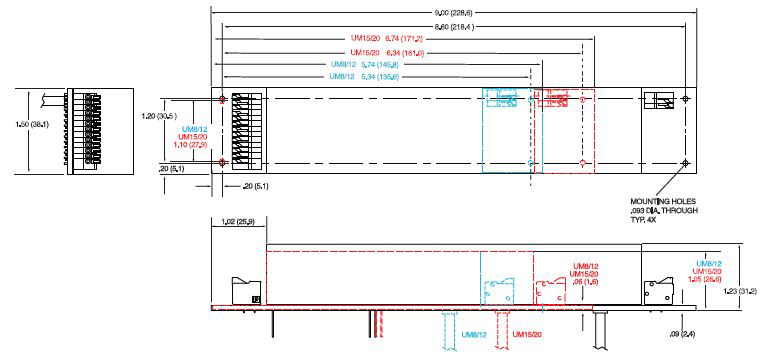
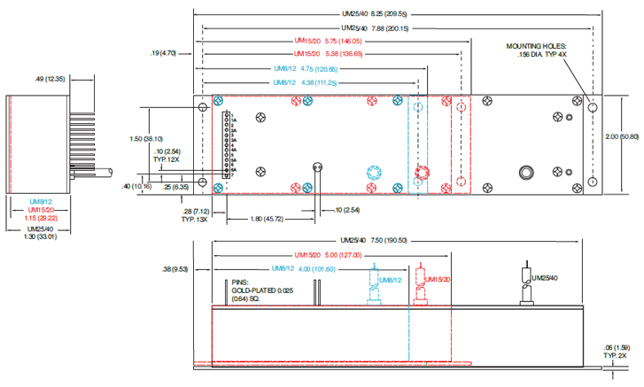
Dimensions:
8kV-12kV: 3.700. L X 1.500. W X 0.990. H (93.98mm X 38.10mm X 25.03mm)
15kV-20kV: 4.700. L X 1.500. W X 0.990. H (119.38mm X 38.10mm X 25.03mm)
25kV-40kV: 6.960. L X 1.600. W X 1.14. H (176.78mm X 40.84mm X 28.87mm)
Weight:
8kV-12kV: 5.7 ounces (162 grams), typical
15kV-20kV: 7.2 ounces (204 grams), typical
25kV-40kV: 13.1 ounces (371 grams), typical
Output Cable:
UM8, UM10, UM12, UM15: TV20 (min. length, 36. (914.4mm)
UM20, UM25: TV30 (min. length, 36. (914.4mm)
UM30, UM35, UM40: TV40 (min. length, 36. (914.4mm)
See product PDF for more specification and features.
UM 4W, 8kV TO 40kV SELECTION TABLE
| Model Number | Output V | Output Current | Ripple(max) %Vp-p | Output Capacitance | Arc Limiting Resistance | I Sense Scaling Full Scale Signal | High Voltage Divider Resistance |
|---|---|---|---|---|---|---|---|
| UM8*4 | 0 to 8kV | 0.5mA | 0.05 | 6830pF | 50kΩ | 5V | 200MΩ |
| UM10*4 | 0 to10kV | 0.4mA | 0.05 | 4380pF | 50kΩ | 2.4V | 300MΩ |
| UM12*4 | 0 to 12kV | 0.333mA | 0.05 | 4380pF | 50kΩ | 3.33V | 300MΩ |
| UM15*4 | 0 to 15kV | 0.266mA | 0.05 | 3220pF | 100kΩ | 1.69V | 400MΩ |
| UM20*4 | 0 to 20kV | 0.2mA | 0.05 | 2310pF | 100kΩ | 1.316V | 550MΩ |
| UM25*4 | 0 to 25kV | 0.16mA | 0.05 | 1540pF | 100kΩ | 1.1V | 800MΩ |
| UM30*4 | 0 to 30kV | 0.133mA | 0.05 | 1370pF | 120kΩ | 0.95V | 900MΩ |
| UM35*4 | 0 to 35kV | 0.115mA | 0.05 | 1370pF | 140kΩ | 0.72V | 900MΩ |
| UM40*4 | 0 to 40kV | 0.1mA | 0.05 | 1370pF | 140kΩ | 1.3V | 900MΩ |
UM 15W, 8kV TO 40kV SELECTION TABLE
| Model Number | Output V | Output Current | Ripple(max) %Vp-p | Output Capacitance | Arc Limiting Resistance | I Sense Scaling Full Scale Signal | High Voltage Divider Resistance |
|---|---|---|---|---|---|---|---|
| UM8*15 | 0 to 8kV | 1.875mA | 0.05 | 6830pF | 50kΩ | 3.75V | 200MΩ |
| UM10*15 | 0 to 10kV | 1.5mA | 0.05 | 4380pF | 50kΩ | 8.152V | 300MΩ |
| UM12*15 | 0 to 12kV | 1.25mA | 0.05 | 4380pF | 50kΩ | 5V | 300MΩ |
| UM15*15 | 0 to 15kV | 1mA | 0.05 | 3220pF | 100kΩ | 5.53V | 400MΩ |
| UM20*15 | 0 to 20kV | 0.75mA | 0.05 | 2310pF | 100kΩ | 4.21V | 550MΩ |
| UM25*15 | 0 to 25kV | 0.6mA | 0.05 | 1540pF | 100kΩ | 3.42V | 800MΩ |
| UM30*15 | 0 to 30kV | 0.5mA | 0.05 | 1370pF | 120kΩ | 2.89V | 900MΩ |
| UM35*15 | 0 to 35kV | 0.429mA | 0.05 | 1370pF | 140kΩ | 2.39V | 900MΩ |
| UM40*15 | 0 to 40kV | 0.375mA | 0.05 | 1370pF | 140kΩ | 4.21V | 900MΩ |
UM 30W, 8kV TO 40kV SELECTION TABLE
| Model Number | Output V | Output Current | Ripple(max) %Vp-p | Output Capacitance | Arc Limiting Resistance | I Sense Scaling Full Scale Signal | High Voltage Divider Resistance |
|---|---|---|---|---|---|---|---|
| UM8*30 | 0 to 8kV | 3.75mA | 0.05 | 6830pF | 50kΩ | 5.36V | 200MΩ |
| UM10*30 | 0 to 10kV | 3mA | 0.05 | 4380pF | 50kΩ | 7.87V | 300MΩ |
| UM12*30 | 0 to 12kV | 2.5mA | 0.05 | 4380pF | 50kΩ | 5V | 300MΩ |
| UM15*30 | 0 to 15kV | 2mA | 0.05 | 3220pF | 100kΩ | 5.29V | 400MΩ |
| UM20*30 | 0 to 20kV | 1.5mA | 0.05 | 2310pF | 100kΩ | 8.15V | 550MΩ |
| UM25*30 | 0 to 25kV | 1.2mA | 0.05 | 1540pF | 100kΩ | 6.56V | 800MΩ |
| UM30*30 | 0 to 30kV | 1mA | 0.05 | 1370pF | 120kΩ | 5.52V | 900MΩ |
| UM35*30 | 0 to 35kV | 0.857mA | 0.05 | 1370pF | 140kΩ | 4.66V | 900MΩ |
| UM40*30 | 0 to 40kV | 0.75mA | 0.05 | 1370pF | 140kΩ | 8.15V | 900MΩ |
STANDARD INTERFACE
| Pin | Signal | Parameters |
|---|---|---|
| 1 | Power Ground Return | +12Vdc or +24Vdc power return/HV return |
| 1A | Signature Resistor | Unique Identifying resistor connected to ground |
| 2 | + Power Input | +12Vdc or +24Vdc power input |
| 2A | OT Output | +5Vdc @ 1mA = Over Temp fault |
| 3 | I Sense | See I Sense text and tables for details |
| 3A | I Mon | 0 to 4.64Vdc = 0 to 100% rated output. Zout < 10kΩ |
| 4 | Enable Input | Low (<0.7V, Isink@1mA)=HV OFF, High (open or >2V)=HV ON |
| 4A | V Mon | 0 to 4.64Vdc = 0 to 100% rated output. Zout < 10kΩ |
| 5 | Signal Ground | Signal Ground |
| 5A | I Pgm | 0 to 4.64Vdc = 0 to 100% rated output. Zin > 47kΩ Leave open for preset current limit @103% of rated output current |
| 6 | Remote Adjust | Positive Polarity Unit: 0 to +4.64VDC = 0 to 100% rated voltage, Zin >1MΩ Negative Polarity Unit: +5VDC to 0.36V = 0 to 100% rated voltage, Zin >100kΩ Leave open if pin 6A (VPgm) is used for programming |
| 6A | V Pgm | 0 to 4.64Vdc = 0 to 100% rated voltage. Zin > 100kΩ Leave open if pin 6 (remote adjust) is used for programming |
| 7 | +5V Reference Output | +5Vdc ±1%, 25ppm/°C. Zout =475Ω |
| 8 | HV Ground Return | HV Ground Return |
| 9 | E Out Monitor | 1000:1 ratio. Polarity of Voltage Monitor signal equals polarity of unit. Accuracy is ±2%, 100ppm/°C. Calibrated with DVM with 10MΩ input impedance |
Grayed out signals are provided for backward legacy compatibility and their use is not required.
Power Ground Return, Signal Ground and HV Ground Return are connected internally. For best performance they should not be connected externally.
LEGACY INTERFACE (L OPTION)
| Pin | Signal | Parameters |
|---|---|---|
| 1 | Power Ground Return | +12Vdc or +24Vdc power return/HV return |
| 2 | + Power Input | +12Vdc or +24Vdc power input |
| 3 | I Sense | See I Sense text and tables for details |
| 4 | Enable Input | Low (<0.7V, Isink@1mA)=HV OFF, High (open or >2V)=HV ON |
| 5 | Signal Ground | Signal Ground |
| 6 | Remote Adjust | Positive Polarity Unit: 0 to +4.64VDC = 0 to 100% rated voltage, Zin >1MΩ Negative Polarity Unit: +5VDC to 0.36V = 0 to 100% rated voltage, Zin >100kΩ |
| 7 | +5V Reference Output | +5Vdc ±1%, 25ppm/°C. Zout =475Ω |
| 8 | HV Ground Return | HV Ground Return |
| 9 | E Out Monitor | 1000:1 ratio. Polarity of Voltage Monitor signal equals polarity of unit. Accuracy is ±2%, 100ppm/°C. Calibrated with DVM with 10MΩ input impedance |
Power Ground Return, Signal Ground and HV Ground Return are connected internally. For best performance they should not be connected externally.
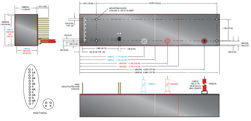
Standard Interface Connections
Fifteen (15) gold plated 0.025˝ (0.64mm) square pins suitable for direct PCB mounting.
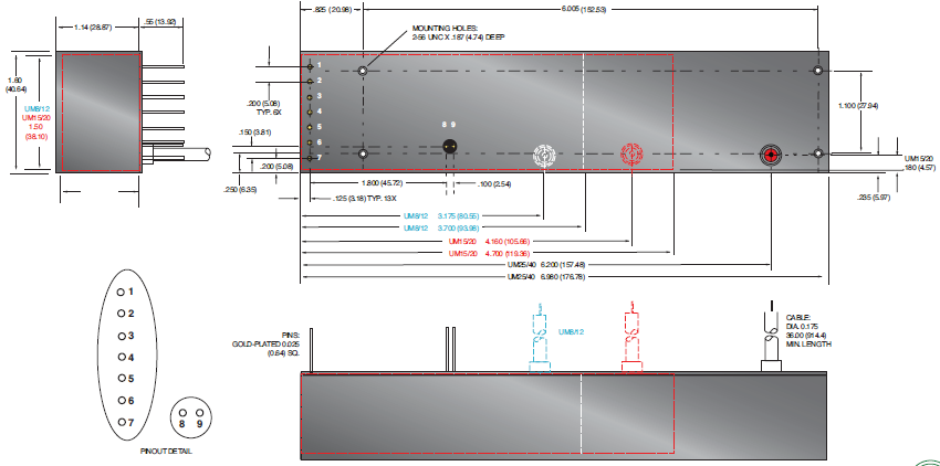
Legacy Interface Connections
Nine (9) gold plated 0.025˝ (0.64mm) square pins suitable for direct PCB mounting.
See mechanical drawing for location and spacing details
Programming and Monitor Signals
Voltage and current programming is done via positive polarity, high input impedance, 0 to 4.64Vdc signals.
Voltage and current monitors are positive polarity, buffered low output impedance 0 to 4.64Vdc signals.
I Mon
The I Mon signal is a true output current monitoring signal. All internal offsets due to feedback divider currents have been compensated for.
Signature Resistor
A unique identifying signature resistor for each type of unit is connected from Pin 1A to ground. Details if desired are available upon request.
I Sense Signal
The polarity of the I Sense signal is opposite of the polarity of the output voltage of the unit that generated it. So a positive output polarity unit creates a negative polarity current monitor signal; while a negative output polarity unit creates a positive polarity current monitoring signal. This signal is clamped to ground internally via a bidirectional transient protection device and the signal is made available via a series connected 47kΩ isolation resistor. Internal HV dividers create a small,
linear offset voltage on this current monitor signal that can be compensated for.
OT Output
The unit is protected by an internal thermostat that will shut the unit off if the case temperature exceeds 65°C. The OT Output signal will change states indicating an over temperature fault has occurred. In order to clear the OT signal and re-enable the unit, the temperature has to drop below 55 degrees C and input power needs to be recycled. For details on unit cooling requirements and the OT Output signal please see the operator’s manual.
Tables & Diagrams
UM8-40 OPTIONS
T Option
Low Temperature Coefficient-
The T Option offers the UM with an improved temperature coefficient. The standard voltage feedback divider is replaced with one having a superior temperature coefficient, resulting in a unit with 25ppm/C° (typical) temperature coefficient.
PHYSICAL INTERFACING
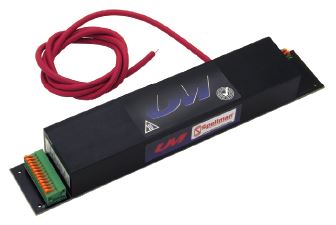
B Option
Terminal Block-
The B Option provides terminal block connections for both the customer interface and high voltage output/return.
This feature can be helpful in situations where frequent wiring changes are anticipated, as in a testing or prototype environment.
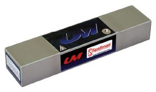
SHIELDING OPTIONS
S Option
RF Tight Shielded Can-
The S Option mounts the UM module inside of a flanged RF tight aluminum can.
SHIELDING OPTIONS (CONT)
M Option
Mu Metal Shield-
UM modules can be fitted with an adhesive backed Mu Metal foil shield to help protect sensitive adjacent circuitry.
Same as standard unit.
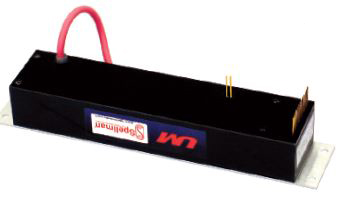
CHASSIS MOUNTING OPTION
E Option
Eared Mounting Plate-
An eared mounting plate is affixed to the top surface of the UM module allowing simple chassis mounting of unit.
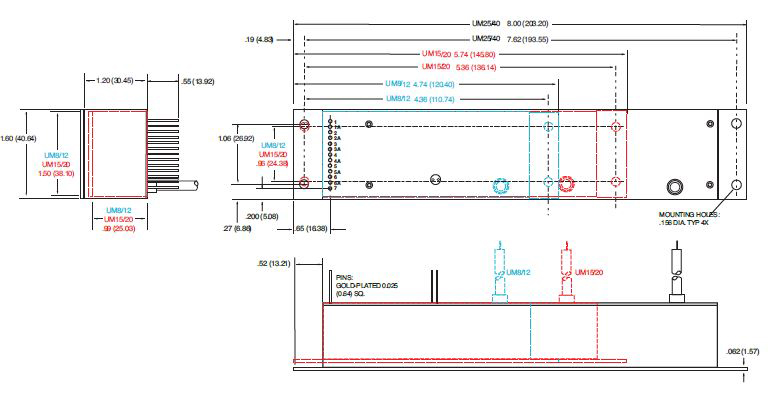
DIMENSIONS: in.[mm]
15 PIN - Standard Interface
9 PIN - Legacy Interface
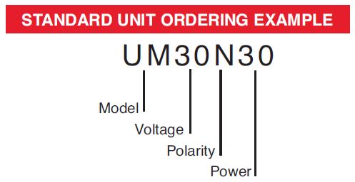
ORDERING INFORMATION
| Voltage | 0 to 8kV | 8 |
| 0 to 10kV | 10 | |
| 0 to 12kV | 12 | |
| 0 to 15kV | 15 | |
| 0 to 20kV | 20 | |
| 0 to 25kV | 25 | |
| 0 to 30kV | 30 | |
| 0 to 35kV | 35 | |
| 0 to 40kV | 40 | |
| Polarity | Positive | P |
| Negative | N | |
| Power | Watts Output | 4 |
| Watts Output | 15 | |
| Watts Output | 30 |
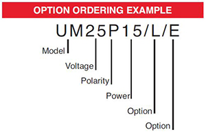
STANDARD UNIT ORDERING EXAMPLE
OPTION ORDERING INFORMATION
| OPTION | OPTION CODE |
|---|---|
|
Legacy Interface |
L |
| Low Temperature Coefficient | T |
| Mu Metal Shield | M |
| RF Tight Shielded Can | S |
| Eared Mounting Plate | E |
| Terminal Block | B |
Frequently Asked Questions
What Is a Safe Level of High Voltage?
Where Can I Obtain Information on High Voltage Safety Practices?
What Kind of High Voltage Connector Do You Use on Your Supplies?
What Do You Mean That the Output Side of the High Voltage Cable on Most Standard Products Is “Unterminated”?
How Should I Ground Your Supply?
Why Is Arcing an Issue for a High Voltage Power Supply?

