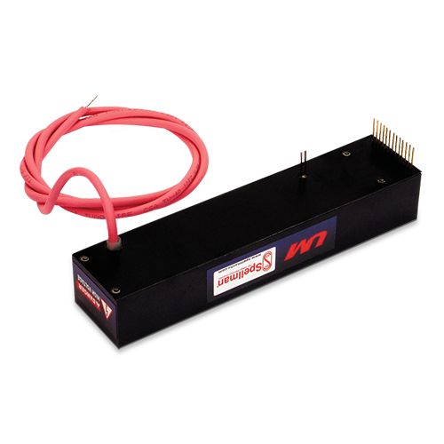
UM8-40 СЕРИЯ
- 9 Voltage Ranges from 8kV to 40kV, Fixed Negative or Positive Polarity
- Available Output Power Increments of 4, 15 and 30 Watts
- Voltage/Current Regulation with Automatic Crossover Control
- Voltage and Current Monitor Signals
- Fully Arc and Short Circuit Protected
- Precision +5V Reference Output
- Comprehensive Standard Interface
- CE listed and RoHS compliant
* Примечание: Все спецификации могут быть изменены без предварительного уведомления. Пожалуйста, ознакомьтесь с английской версией PDF этой спецификации для получения последней актуальной информации об оборудовании.

Высоковольтные источники питания постоянного тока
Форма, размер и функциональность:
Производимые компанией Spellman высоковольтные модули серии UM, устанавливаемые на печатную плату, обладают такими формой, размером и функциями, которые позволяют заменить собой имеющиеся в настоящее время и производимые в коммерческом масштабе блоки, предлагая при этом дополнительные функции и преимущества по конкурентной цене. Благодаря использованию патентованной технологии преобразования энергии и 60-летнему опыту создания высоковольтной аппаратуры компании Spellman эти высоковольтные модули, изготовленные на основе технологии поверхностного монтажа, обеспечивают улучшенные технические характеристики, надежность и более простую системную интеграцию при более низких затратах, если сравнивать с конкурентами.
Улучшенная технология преобразования энергии:
В преобразователях серии UM используется запатентованная топология преобразования энергии с коммутацией по нулевому напряжению, обеспечивающая исключительную эффективность, специфический низкий уровень шумов и пульсаций. Уровень излучений снижен по сравнению с обычными коммутационными топологиями, и потребность в экранировании блока от соседних схем сводится к минимуму или вообще отпадает. Высоковольтное выходное напряжение генерируется с помощью высоковольтного повышающего трансформатора с ферритовым сердечником, который питает однополупериодный умножитель напряжения Кокрофта-Уолтона для получения заданного высокого напряжения на выходе.
Благодаря фиксированной высокой скорости преобразования частоты выходная емкость мала, и накапливаемая энергия минимальна. Благодаря использованию резисторов, ограничивающих всплески напряжения, с хорошим запасом номинала и быстродействующего токового контура все блоки полностью защищены от дуги и короткого замыкания.
Контроль и регулировка:
Фактически генерируемое выходное напряжение поступает на делитель с высоким импедансом и используется в качестве сигнала обратной связи по напряжению. Сигнал обратной связи по току формируется чувствительным к току резистором на нижней стороне обратного контура цепи высоковольтного выхода. Эти два высокоточных опорных относительно «земли» сигнала обратной связи используются для точной регулировки и контроля блоков в дополнение к внешнему контролю. Благодаря уникальной топологии преобразователя серии UM он может обеспечивать полный ток в нагрузках с низким импедансом, или даже короткое замыкание. В стандартных блоках выходной ток ограничен значением 10 % от максимального номинального тока.
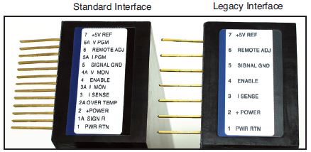
Стандартный интерфейс:
Интерфейс модулей серии UM производства компании Spellman обеспечивает возможность программирования тока и буферизованные сигналы контроля напряжения и тока положительной полярности с низким выходным импедансом (от нуля до +4,64 В пост. тока = от нуля до максимального номинального значения). Имеется вход для программирования напряжения, причем значения от 0 до +4,64 В пост. тока соответствуют значениям от 0 до 100 % номинального напряжения.
Возможность программирования тока позволяет пользователю устанавливать ограничение по току для блока в любой точке от 0 до 100% максимального номинального тока. Эта особенность дает преимущества там, где требуется величина тока, меньше максимальной, например, в случае защиты чувствительной нагрузки. Буферизированные сигналы контроля напряжения и тока с низким импедансом могут использоваться для непосредственного управления внешними схемами, сводя к минимуму влияние загруженности и помех. Эти функции избавляют пользователя от расходов на буферную схему внешнего интерфейса, повышая общую целостность сигнала.
Доступ к этому стандартному интерфейсу осуществляется с помощью ряда из 13 контактов с шагом 2,54 мм. Чтобы получить старый интерфейс (7 контактов с шагом 5,8 мм), совместимый с имеющимися сейчас блоками промышленного производства, нужно заказать опцию «L».
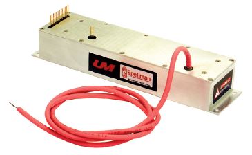
Механические аспекты и условия окружающей среды:Устройства серии UM представляют собой твердотельные герметичные, устанавливаемые на печатную плату преобразователи в пластмассовом корпусе. Все блоки залиты компаундом на кремниевой основе, значительно более легким, чем эпоксидная смола. Модуль надежно крепится к печатной плате незаземленными крепежными винтами 2-56, снимающими любое давление на контакты интерфейса. Предусмотрены также монтажные пластины, скобы и варианты монтажа с фланцем Высоковольтное выходное напряжение снимается с высоковольтного провода соответствующего номинала с минимальной длиной 914,4 мм.
Соответствие нормативным документам:
Соответствует Директиве по электромагнитной совместимости 2004/108/EC и Директиве по низковольтным устройствам 2006/95/EC. Соответствует требованиям 2002/95/EC, RoHS. Устройства признаны соответствующими требованиям UL/CUL, файл E227588.
Технические характеристики
(Rev. 128074-001 REV. R)
Input Voltage:
12Vdc for 4W, 24Vdc for 15W and 30W
Nominal Voltage Range:
11Vdc to 30Vdc for 4W, 23Vdc to 30Vdc for 15W and 30W 4W units can operate at 24Vdc input with no deratings or damage to unit
Input Current: (typical)
Disabled: 10mA @ 24Vdc
Full output, no load: 160mA @ 24Vdc, 300mA @ 12Vdc
Full output, full load:
4 watt units: 330mA @ 24Vdc, 640mA @ 12Vdc
15 watt units: 850mA @ 24Vdc
30 watt units: 1590mA @ 24Vdc
Voltage Regulation:
Line: <0.01% Load: <0.01%
Current Regulation:
Line: <0.01% Load: <0.01%
Stability:
0.01% per 8 hours, 0.02% per day after 30 min. warmup
Accuracy:
2% on all programming and monitoring, except I Sense 10%
Temperature Coefficient: (typical)
Standard: 100ppm/°C
Optional: 25ppm/°C (T Option)
Environmental:
Temperature Range:
Operating: -40°C to 65°C case temperature
Storage: -55°C to 105°C, non operational
Humidity: 10% to 90%, non-condensing.
Cooling:
Convection cooled, typical. 30 watt units operating at full power might require additional cooling to maintain case temperature below 65°C. Methods may include: forced air cooling, use of heat sink or metal case, etc. It is the user’s responsibility to maintain the case temperature below 65°C. Damage to the power supply due to inadequate cooling is considered misuse and repairs will not be covered under warranty.
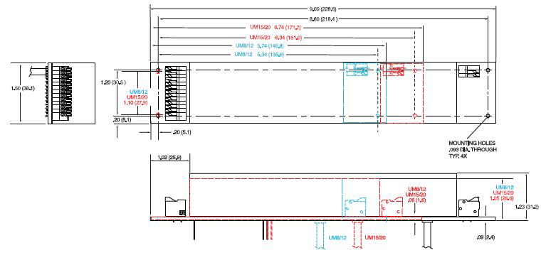
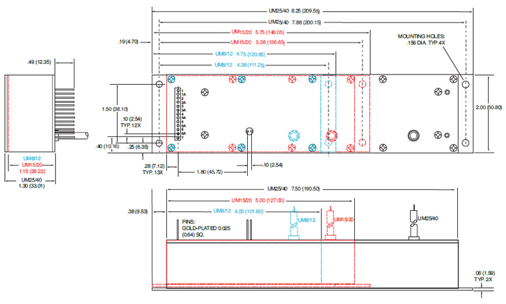
Dimensions:
8kV-12kV: 3.700. L X 1.500. W X 0.990. H (93.98mm X 38.10mm X 25.03mm)
15kV-20kV: 4.700. L X 1.500. W X 0.990. H (119.38mm X 38.10mm X 25.03mm)
25kV-40kV: 6.960. L X 1.600. W X 1.14. H (176.78mm X 40.84mm X 28.87mm)
Weight:
8kV-12kV: 5.7 ounces (162 grams), typical
15kV-20kV: 7.2 ounces (204 grams), typical
25kV-40kV: 13.1 ounces (371 grams), typical
Output Cable:
UM8, UM10, UM12, UM15: TV20 (min. length, 36. (914.4mm)
UM20, UM25: TV30 (min. length, 36. (914.4mm)
UM30, UM35, UM40: TV40 (min. length, 36. (914.4mm)
See product PDF for more specification and features.
UM 4W, 8kV TO 40kV SELECTION TABLE
| Model Number | Output V | Output Current | Ripple(max) %Vp-p | Output Capacitance | Arc Limiting Resistance | I Sense Scaling Full Scale Signal | High Voltage Divider Resistance |
|---|---|---|---|---|---|---|---|
| UM8*4 | 0 to 8kV | 0.5mA | 0.05 | 6830pF | 50kΩ | 5V | 200MΩ |
| UM10*4 | 0 to10kV | 0.4mA | 0.05 | 4380pF | 50kΩ | 2.4V | 300MΩ |
| UM12*4 | 0 to 12kV | 0.333mA | 0.05 | 4380pF | 50kΩ | 3.33V | 300MΩ |
| UM15*4 | 0 to 15kV | 0.266mA | 0.05 | 3220pF | 100kΩ | 1.69V | 400MΩ |
| UM20*4 | 0 to 20kV | 0.2mA | 0.05 | 2310pF | 100kΩ | 1.316V | 550MΩ |
| UM25*4 | 0 to 25kV | 0.16mA | 0.05 | 1540pF | 100kΩ | 1.1V | 800MΩ |
| UM30*4 | 0 to 30kV | 0.133mA | 0.05 | 1370pF | 120kΩ | 0.95V | 900MΩ |
| UM35*4 | 0 to 35kV | 0.115mA | 0.05 | 1370pF | 140kΩ | 0.72V | 900MΩ |
| UM40*4 | 0 to 40kV | 0.1mA | 0.05 | 1370pF | 140kΩ | 1.3V | 900MΩ |
UM 15W, 8kV TO 40kV SELECTION TABLE
| Model Number | Output V | Output Current | Ripple(max) %Vp-p | Output Capacitance | Arc Limiting Resistance | I Sense Scaling Full Scale Signal | High Voltage Divider Resistance |
|---|---|---|---|---|---|---|---|
| UM8*15 | 0 to 8kV | 1.875mA | 0.05 | 6830pF | 50kΩ | 3.75V | 200MΩ |
| UM10*15 | 0 to 10kV | 1.5mA | 0.05 | 4380pF | 50kΩ | 8.152V | 300MΩ |
| UM12*15 | 0 to 12kV | 1.25mA | 0.05 | 4380pF | 50kΩ | 5V | 300MΩ |
| UM15*15 | 0 to 15kV | 1mA | 0.05 | 3220pF | 100kΩ | 5.53V | 400MΩ |
| UM20*15 | 0 to 20kV | 0.75mA | 0.05 | 2310pF | 100kΩ | 4.21V | 550MΩ |
| UM25*15 | 0 to 25kV | 0.6mA | 0.05 | 1540pF | 100kΩ | 3.42V | 800MΩ |
| UM30*15 | 0 to 30kV | 0.5mA | 0.05 | 1370pF | 120kΩ | 2.89V | 900MΩ |
| UM35*15 | 0 to 35kV | 0.429mA | 0.05 | 1370pF | 140kΩ | 2.39V | 900MΩ |
| UM40*15 | 0 to 40kV | 0.375mA | 0.05 | 1370pF | 140kΩ | 4.21V | 900MΩ |
UM 30W, 8kV TO 40kV SELECTION TABLE
| Model Number | Output V | Output Current | Ripple(max) %Vp-p | Output Capacitance | Arc Limiting Resistance | I Sense Scaling Full Scale Signal | High Voltage Divider Resistance |
|---|---|---|---|---|---|---|---|
| UM8*30 | 0 to 8kV | 3.75mA | 0.05 | 6830pF | 50kΩ | 5.36V | 200MΩ |
| UM10*30 | 0 to 10kV | 3mA | 0.05 | 4380pF | 50kΩ | 7.87V | 300MΩ |
| UM12*30 | 0 to 12kV | 2.5mA | 0.05 | 4380pF | 50kΩ | 5V | 300MΩ |
| UM15*30 | 0 to 15kV | 2mA | 0.05 | 3220pF | 100kΩ | 5.29V | 400MΩ |
| UM20*30 | 0 to 20kV | 1.5mA | 0.05 | 2310pF | 100kΩ | 8.15V | 550MΩ |
| UM25*30 | 0 to 25kV | 1.2mA | 0.05 | 1540pF | 100kΩ | 6.56V | 800MΩ |
| UM30*30 | 0 to 30kV | 1mA | 0.05 | 1370pF | 120kΩ | 5.52V | 900MΩ |
| UM35*30 | 0 to 35kV | 0.857mA | 0.05 | 1370pF | 140kΩ | 4.66V | 900MΩ |
| UM40*30 | 0 to 40kV | 0.75mA | 0.05 | 1370pF | 140kΩ | 8.15V | 900MΩ |
STANDARD INTERFACE
| Pin | Signal | Parameters |
|---|---|---|
| 1 | Power Ground Return | +12Vdc or +24Vdc power return/HV return |
| 1A | Signature Resistor | Unique Identifying resistor connected to ground |
| 2 | + Power Input | +12Vdc or +24Vdc power input |
| 2A | OT Output | +5Vdc @ 1mA = Over Temp fault |
| 3 | I Sense | See I Sense text and tables for details |
| 3A | I Mon | 0 to 4.64Vdc = 0 to 100% rated output. Zout < 10kΩ |
| 4 | Enable Input | Low (<0.7V, Isink@1mA)=HV OFF, High (open or >2V)=HV ON |
| 4A | V Mon | 0 to 4.64Vdc = 0 to 100% rated output. Zout < 10kΩ |
| 5 | Signal Ground | Signal Ground |
| 5A | I Pgm | 0 to 4.64Vdc = 0 to 100% rated output. Zin > 47kΩ Leave open for preset current limit @103% of rated output current |
| 6 | Remote Adjust | Positive Polarity Unit: 0 to +4.64VDC = 0 to 100% rated voltage, Zin >1MΩ Negative Polarity Unit: +5VDC to 0.36V = 0 to 100% rated voltage, Zin >100kΩ Leave open if pin 6A (VPgm) is used for programming |
| 6A | V Pgm | 0 to 4.64Vdc = 0 to 100% rated voltage. Zin > 100kΩ Leave open if pin 6 (remote adjust) is used for programming |
| 7 | +5V Reference Output | +5Vdc ±1%, 25ppm/°C. Zout =475Ω |
| 8 | HV Ground Return | HV Ground Return |
| 9 | E Out Monitor | 1000:1 ratio. Polarity of Voltage Monitor signal equals polarity of unit. Accuracy is ±2%, 100ppm/°C. Calibrated with DVM with 10MΩ input impedance |
Grayed out signals are provided for backward legacy compatibility and their use is not required.
Power Ground Return, Signal Ground and HV Ground Return are connected internally. For best performance they should not be connected externally.
LEGACY INTERFACE (L OPTION)
| Pin | Signal | Parameters |
|---|---|---|
| 1 | Power Ground Return | +12Vdc or +24Vdc power return/HV return |
| 2 | + Power Input | +12Vdc or +24Vdc power input |
| 3 | I Sense | See I Sense text and tables for details |
| 4 | Enable Input | Low (<0.7V, Isink@1mA)=HV OFF, High (open or >2V)=HV ON |
| 5 | Signal Ground | Signal Ground |
| 6 | Remote Adjust | Positive Polarity Unit: 0 to +4.64VDC = 0 to 100% rated voltage, Zin >1MΩ Negative Polarity Unit: +5VDC to 0.36V = 0 to 100% rated voltage, Zin >100kΩ |
| 7 | +5V Reference Output | +5Vdc ±1%, 25ppm/°C. Zout =475Ω |
| 8 | HV Ground Return | HV Ground Return |
| 9 | E Out Monitor | 1000:1 ratio. Polarity of Voltage Monitor signal equals polarity of unit. Accuracy is ±2%, 100ppm/°C. Calibrated with DVM with 10MΩ input impedance |
Power Ground Return, Signal Ground and HV Ground Return are connected internally. For best performance they should not be connected externally.
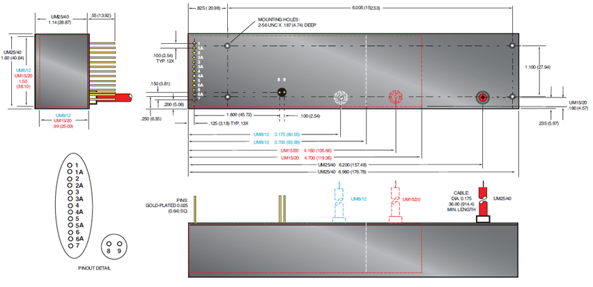
Standard Interface Connections
Fifteen (15) gold plated 0.025˝ (0.64mm) square pins suitable for direct PCB mounting.
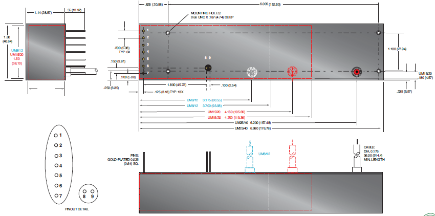
Legacy Interface Connections
Nine (9) gold plated 0.025˝ (0.64mm) square pins suitable for direct PCB mounting.
See mechanical drawing for location and spacing details
Programming and Monitor Signals
Voltage and current programming is done via positive polarity, high input impedance, 0 to 4.64Vdc signals.
Voltage and current monitors are positive polarity, buffered low output impedance 0 to 4.64Vdc signals.
I Mon
The I Mon signal is a true output current monitoring signal. All internal offsets due to feedback divider currents have been compensated for.
Signature Resistor
A unique identifying signature resistor for each type of unit is connected from Pin 1A to ground. Details if desired are available upon request.
I Sense Signal
The polarity of the I Sense signal is opposite of the polarity of the output voltage of the unit that generated it. So a positive output polarity unit creates a negative polarity current monitor signal; while a negative output polarity unit creates a positive polarity current monitoring signal. This signal is clamped to ground internally via a bidirectional transient protection device and the signal is made available via a series connected 47kΩ isolation resistor. Internal HV dividers create a small,
linear offset voltage on this current monitor signal that can be compensated for.
OT Output
The unit is protected by an internal thermostat that will shut the unit off if the case temperature exceeds 65°C. The OT Output signal will change states indicating an over temperature fault has occurred. In order to clear the OT signal and re-enable the unit, the temperature has to drop below 55 degrees C and input power needs to be recycled. For details on unit cooling requirements and the OT Output signal please see the operator’s manual.
Таблицы и диаграммы
UM8-40 OPTIONS
T Option
Low Temperature Coefficient-
The T Option offers the UM with an improved temperature coefficient. The standard voltage feedback divider is replaced with one having a superior temperature coefficient, resulting in a unit with 25ppm/C° (typical) temperature coefficient.
PHYSICAL INTERFACING
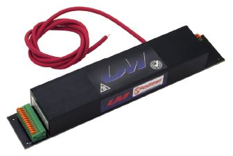
B Option
Terminal Block-
The B Option provides terminal block connections for both the customer interface and high voltage output/return.
This feature can be helpful in situations where frequent wiring changes are anticipated, as in a testing or prototype environment.
SHIELDING OPTIONS
S Option
RF Tight Shielded Can-
The S Option mounts the UM module inside of a flanged RF tight aluminum can.
SHIELDING OPTIONS (CONT)
M Option
Mu Metal Shield-
UM modules can be fitted with an adhesive backed Mu Metal foil shield to help protect sensitive adjacent circuitry.
Same as standard unit.
CHASSIS MOUNTING OPTION
E Option
Eared Mounting Plate-
An eared mounting plate is affixed to the top surface of the UM module allowing simple chassis mounting of unit.
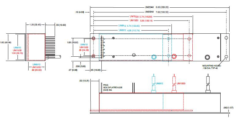
DIMENSIONS: in.[mm]
15 PIN - Standard Interface
9 PIN - Legacy Interface
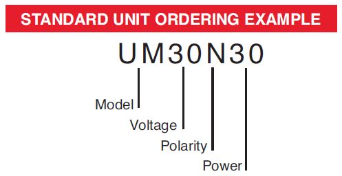
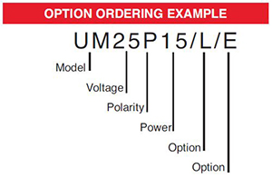
ORDERING INFORMATION
| Voltage | 0 to 8kV | 8 |
| 0 to 10kV | 10 | |
| 0 to 12kV | 12 | |
| 0 to 15kV | 15 | |
| 0 to 20kV | 20 | |
| 0 to 25kV | 25 | |
| 0 to 30kV | 30 | |
| 0 to 35kV | 35 | |
| 0 to 40kV | 40 | |
| Polarity | Positive | P |
| Negative | N | |
| Power | Watts Output | 4 |
| Watts Output | 15 | |
| Watts Output | 30 |
STANDARD UNIT ORDERING EXAMPLE
OPTION ORDERING INFORMATION
| OPTION | OPTION CODE |
|---|---|
|
Legacy Interface |
L |
| Low Temperature Coefficient | T |
| Mu Metal Shield | M |
| RF Tight Shielded Can | S |
| Eared Mounting Plate | E |
| Terminal Block | B |
Frequently Asked Questions
What Is a Safe Level of High Voltage?
Where Can I Obtain Information on High Voltage Safety Practices?
What Kind of High Voltage Connector Do You Use on Your Supplies?
What Do You Mean That the Output Side of the High Voltage Cable on Most Standard Products Is “Unterminated”?
How Should I Ground Your Supply?
Why Is Arcing an Issue for a High Voltage Power Supply?

