STA СЕРИЯ
- 4 кВт на одном шасси 3U (133 мм)
- Модели напряжением от 1 до 70 кв
- Дистанционный аналоговый и Ethernet-интерфейс
- Защита от дуги и короткого замыкания
- Возможность настройки функций пользователем через интерфейс Ethernet
- Возможность изготовления в соответствии с требованиями производителя оригинального оборудования
* Примечание: Все спецификации могут быть изменены без предварительного уведомления. Пожалуйста, ознакомьтесь с английской версией PDF этой спецификации для получения последней актуальной информации об оборудовании.
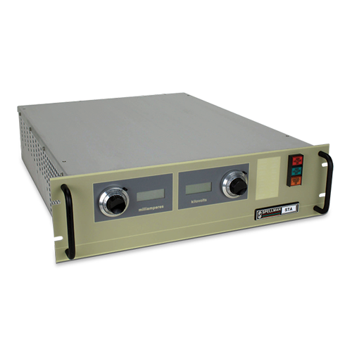
4kW High Voltage Power Supplies
Высоковольтные источники питания серии STA мощностью 4 кВт, поставляются с положительной или отрицательной полярностью. В состав серии входят 15 моделей с диапазоном выходных напряжений от 1 до 70 кВ. Полнофункциональная передняя панель позволяет с легкостью управлять источником локально, а развитый аналоговый интерфейс обеспечивает комплексное дистанционное управление. Стандартный интерфейс Ethernet и цифровой интерфейс RS-232 упрощают интегрирование блоков STA во внешние системы. Инвертор на биполярных транзисторах (IGBT) конструктивно устойчив к отказам и идеален при повышенных требованиях, например, в полупроводниковой промышленности или при вакуумном напылении. Множество рабочих функций настраивается в зависимости от требований пользователя.
Типовые применения:
- Ионное легирование
- Обработка полупроводников
- Электронно-лучевая сварка
- Зарядка конденсаторов
- Радиопередатчики высокой мощности
- Электростатические электрофильтры
- Рентгеновские системы
Технические характеристики
(Rev. 128104-001 REV. K)
HARDWARE BASED OPTIONS
BFP - Blank Front Panel
HS - High Stability
LL(X) - High Voltage Cable Length
1PH - 180-264Vac, Single Phase Input
SOFTWARE CONFIGURABLE FEATURES
Adjustable Overload Trip
Arc Trip Count
Arc Quench Time
Arc Re-Ramp Time
Constant Power Control
Adjustable Power Trip
Slow Start Ramp Times
SPECIFICATIONS
Input Voltage:
Standard: 180-264Vac, 50/60Hz, three phase, 90% efficiency, 0.85 power factor
Optional: 180-264Vac 50/60Hz, single phase (1PH)
Input Current:
Standard: 180-264Vac, three phase 17 amps, maximum
Optional: 180-264Vac, single phase 38 amps, maximum
Output Voltage:
15 models from 1kV to 70kV. Each model is available
with positive or negative outputs.
Local Output Controls:
Voltage and current are continuously adjustable over entire range via ten-turn potentiometers with lockable counting dials.
Voltage Regulation:
Load: 0.05% of full voltage +500mV for full load change.
Line: 0.05%of full voltage +500mV over specified input range.
Current Regulation:
Load: 0.05% of full current ±100µA for any voltage change.
Line: 0.05% of full current over specified input range.
Ripple:
0.1% p-p +1Vrms
Stability:
0.02%hr. after 1 hour warm-up.
Temperature Coefficient:
100ppm/°C. Higher stability (50ppm/°C) available on special order via the HS option
Environmental:
Temperature Range:
Operating: 0°C to 40°C
Storage: -40°C to 85°C
Humidity:
10% to 90% RH, non-condensing.
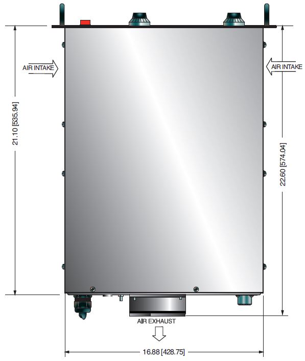
Cooling:
Forced air; inlet through side panels, outlet at rear panel
Metering:
Digital voltage and current meters, accurate to within 1%
System Status Display:
“Dead Front” type indicators provide status of up to 12 system operations including voltage and current regulation, fault conditions and circuit control.
Analog Interface Connector:
50 pin female D connector
High Voltage Output Cable:
A detachable 10’ (3.05m) long shielded HV cable is provided
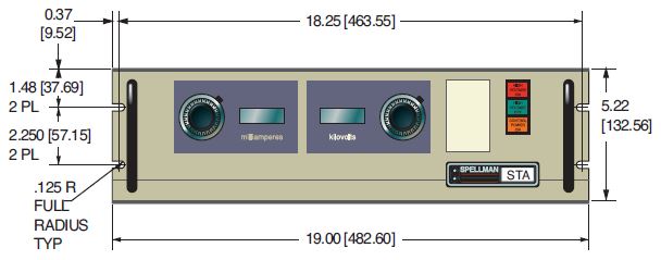
Dimensions:
1kV to 70kV: 5.25. (3U)H X 19. W X 21. D (133mm x 482mm x 533mm)
Weight:
1kV to 8kV: 46 lbs. (20.87kg)
10kV to 70kV: 58 lbs. (26.31kg)
Individual kV models may vary
Regulatory Approvals:
Compliant to EEC EMC Directive. Compliant to EEC Low Voltage Directive. RoHS Compliant.
Digital Interface
The STA features a standard RS-232 and Ethernet digital interface. Utilizing these standard digital interfaces can dramatically simplify power supply interfacing requirements saving the user both time and money, while enhancing functionality and overall capability. Spellman provides a GUI with the STA that allows the customer to both customize operational features of the STA while also providing basic power supply operational features.
Arc Intervention
Spellman’s STA power supplies have an arc intervention feature that senses arc currents via a fast acting current sense transformer. The purpose of the arc intervention circuitry is to prevent power supply damage from continuous, long term arcing. The factory default configuration will trip off the unit with an Arc Fault if 4 arcs occur in a 10 second time period. Customers can change basic arc intervention parameters (Arc Count, Arc Quench, Reramp Time, and Window Time) within preset limits via the digital interface; customized units can be provided for unique arc prone environments, contact Spellman for details.
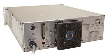
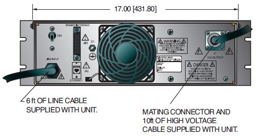
STA rear panel shown with local operation plug installed in 50 pin D connector
Electronic Component (Power Source)
STA series is intended for installation as a component of a system. It is designed to meet CE standards, with conditions of acceptance often being: customer provided enclosure mounting, EMC filtering, and appropriate protection, and isolation devices. The STA series is not intended to be operated by end users as a stand-alone device. The STA series power supply can only be fully assessed when installed within a system, and as a component part within that system.
STA SELECTION TABLE
| Maximum Rating | Model Number | |
|---|---|---|
| kV | mA | |
| 1 | 4,000 | STA1*4 |
| 2 | 2,000 | STA2*4 |
| 3 |
1,333 | STA3*4 |
| 4 | 1,000 | STA4*4 |
| 6 |
667 | STA6*4 |
| 8 | 500 | STA8*4 |
| 10 | 400 | STA10*4 |
| 12 | 333 | STA12*4 |
| 15 | 267 | STA15*4 |
| 20 |
200 | STA20*4 |
| 30 |
133 | STA30*4 |
| 40 | 100 | STA40*4 |
| 50 |
80 | STA50*4 |
| 60 |
67 | STA60*4 |
| 70 | 57 | STA70*4 |
*Substitute “P” for positive polarity and “N” for negative polarity. Polarity must be specified at time of order.
JB1 STA ANALOG INTERFACE— 50 PIN FEMALE D CONNECTOR
| Pin | Signal | Parameters |
|---|---|---|
| 1 | Power Supply Common | Power Supply Ground |
| 2 | Reset/HV Inhibit | Normally open, Low = Reset/Inhibit |
| 3 | External Interlock |
+24Vdc @ open, <25mA @ closed |
| 4 | External Interlock Return |
Return for External Interlock |
| 5 | mA Test Point |
0-10Vdc = 0-100% rated output, Zout= 1KΩ, 1% |
| 6 | kV Test Point |
0-10Vdc = 0-100% rated output, Zout= 1KΩ, 1% |
| 7 | +10Vdc Reference Output |
+10Vdc @ 1mA |
| 8 | mA Program Input |
0-10Vdc = 0-100% rated output, Zin>10MΩ |
| 9 | Local mA Program Output |
0-10Vdc = 0-100% rated output, front panel pot |
| 10 | kV Program Input |
0-10Vdc = 0-100% rated output, Zin>10MΩ |
| 11 | Local kV Program Output |
0-10Vdc = 0-100% rated output, front panel pot |
| 12 | Remote Power On Output |
+24Vdc @ open, 2A peak, 1Adc @ closed |
| 13 | Remote Power On Return |
Return for Remote Power On |
| 14 | Remote HV Off | +24Vdc @ open, 2A peak, 1Adc @ closed, connect to pin15 for front panel operation |
| 15 | Remote HV Off/On Common |
HV On/Off Common |
| 16 | Remote HV On | +24Vdc @ open, 2A peak, 1Adc @ closed, momentarily connect to pin 15 enable high voltage |
| 17 | HV Off Indicator | +24Vdc @ 25mA = HV Off |
| 18 | HV On Indicator |
+24Vdc @ 25mA = HV On |
| 19 | Power Supply Common |
Supply Ground |
| 20 | +24Vdc Output |
+24Vdc @ 100mA, maximum |
| 21 | Voltage Mode Status | Open Collector, Low = Active |
| 22 | Current Mode Status |
Open Collector, Low = Active |
| 23 | Power Mode Status |
Open Collector, Low = Active |
| 24 | Interlock Closed Status |
Open Collector, Low = Active |
| 25 | Power Test Point |
0-10Vdc = 0-100% rated output, Zout= 5KΩ, 1% |
| 26 | Spare | |
| 27 | Spare | |
| 28 | Remote Overvoltage Adjust |
0-10Vdc = 0-100% rated output |
| 29 | Over Power Fault |
Open Collector, Low = Active |
| 30 | Over Voltage Fault |
Open Collector, Low = Active |
| 31 | Over Current Fault |
Open Collector, Low = Active |
| 32 | System Fault |
Open Collector, Low = Active |
| 33 | RGLT Error Fault |
Open Collector, Low = Active |
| 34 | Arc |
Open Collector, Low = Active |
| 35 | Over Temp Fault |
Open Collector, Low = Active |
| 36 | AC Fault |
Open Collector, Low = Active |
| 37 | Spare | |
| 38 | Spare | |
| 39 | Spare | |
| 40 | Spare | |
| 41 | Spare | |
| 42 | Remote Power Program Input |
0-10Vdc = 0-100% rated output, Zin>10MΩ |
| 43 | Local Power Program Output |
0-10Vdc = 0-100% rated output, internal pot |
| 44 | +5Vdc Output |
+5Vdc @ 100mA, maximum |
| 45 | +15Vdc Output |
+15Vdc @ 100mA, maximum |
| 46 | -15Vdc Output |
-15Vdc @ 10mA, maximum |
| 47 | RS232 Tx | |
| 48 | RS232 Rx | |
| 49 | RS232 GND | |
| 50 | Power Supply Common |
Power Supply Ground |
Таблицы и диаграммы
DIMENSIONS: in.[mm]
FRONT VIEW
TOP VIEW
BACK VIEW
Frequently Asked Questions
What Is a Safe Level of High Voltage?
What Is an “External Interlock”?
Where Can I Obtain Information on High Voltage Safety Practices?
What Do You Mean That the Output Side of the High Voltage Cable on Most Standard Products Is “Unterminated”?
How Should I Ground Your Supply?
Why Is Arcing an Issue for a High Voltage Power Supply?
Application Notes AN-13 – Arc Intervention Circuitry and External Series Limiting Resistors
Application Notes AN-14 – The Limits of Front Panel Digital Meters
Application Notes AN-15 – 3.5 And 4.5 Digit Meter Displays Explained
Application Notes AN-18 – Current Loop/Arc Detection Circuitry
Application Notes AN-19 – High Voltage Cable Lengths Discussed

