uXRB130P65
- 1つのコンパクトなアセンブリに統合されたX線管と制御電子機器
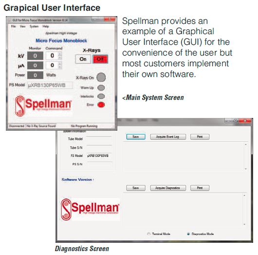
- 診断および操作ログへのアクセスを提供する標準RS-232デジタルインターフェイス
- 標準のWindowsテストGUI
- 狭ビーム用の7ミクロン焦点スポット
- ワイドビーム用の8ミクロン焦点スポット
- 10mm / 14mmのスポットからウィンドウの間隔により、高い幾何学的拡大率を実現
*注:すべての仕様は予告なく変更される場合があります。 最新のリビジョンについては、このデータシートの 英語版PDF を参照してください。
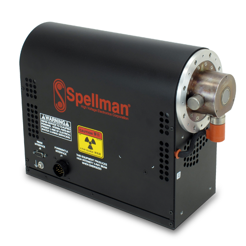
130kV @ 65W X-Ray Source
スペルマンのuXRB130P65マイクロフォーカスMonoblock®X線源は、内部マイクロフォーカスX線管に最大130kV @ 65Wで給電する高解像度イメージングアプリケーション向けに設計されています。24Vdc入力電圧、小型パッケージサイズ、標準RS-232デジタルインターフェイスなどの機能により、uXRB130P65をX線システムに簡単に統合できます。動作電圧の範囲で最適化された小型で丸い焦点サイズ、高倍率、安定した高輝度出力を組み合わせることで、歪みのない優れた品質の2Dおよび3D画像を提供します。
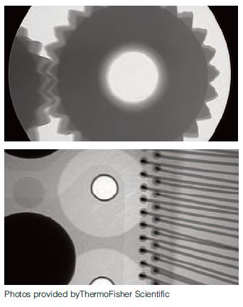
主なアプリケーション
工業用X線:
- 回路基板および電子部品の検査
- 金属およびプラスチック部品の高解像度非破壊検査
- 産業用マイクロCT
- バッテリー検査
医用X線:
- 生命科学アプリケーション用のマイクロCT
Specifications
(Ref. 128082-001 REV. E)
Options:
WB Wide Beam
ET Extended Tube (wide beam only)
LW Light Weight
The uXRB130P65 is ideal for applications such as printed circuit board inspection, battery inspection and industrial/medical micro CT.
Specifications:
Narrow Beam Benefits (Standard):
The small round spot is optimized over the range of kV and power to provide distortion free images. Operated at 4 watts yields a 6 micron spot for high resolution imaging. The 14mm spot to window spacing offers high geometric magnification.
Narrow Beam X-Ray Characteristics (Standard):
Spot Ellipticity: ±20% @ 16 watts, 130kV (either axis referred to average)
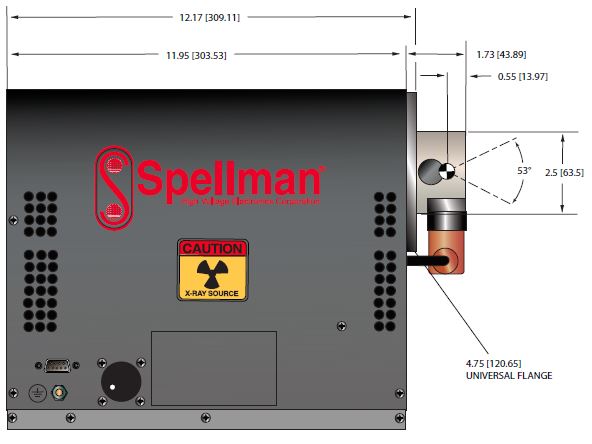
Beam Geometry: ≥ 53°, round beam, uniform beam profile in any direction
Spot to Window Spacing: 14mm ±0.5mm
Window Diameter ≈19mm
Window Material and Thickness: Beryllium, 0.25mm
Target Material: Tungsten
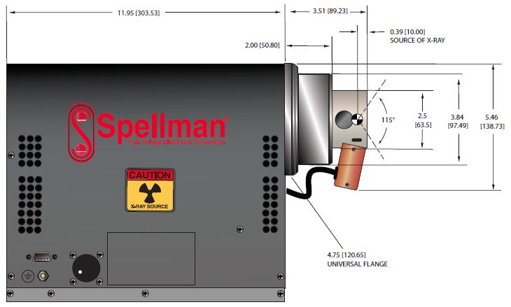
Wide Beam Benefits (WB Option):
The 115 degree round beam is well suited for automated
inspection where a large field of view is required for maximum throughput or off angled views. The 10mm spot to window spacing provides superior high geometric
magnification.
Wide Beam X-Ray Characteristics (WB Option):
Voltage measured across the X-Ray tube is within ±2% of the programmed value
Spot Ellipticity:
±20% @ 16 watts, 130kV (either axis referred to average)
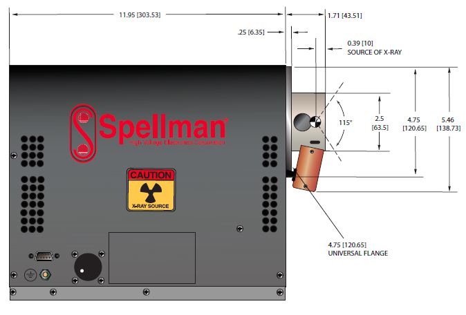
Cone of Illumination: 115°, round beam, uniform beam profile in any direction
Spot to Window Spacing: 10mm ±0.5mm
Window Diameter (uncollimated): ≈38mm
Window Material and Thickness: Beryllium, 0.51mm
Target Material: Tungsten
X-Ray Leakage: Behind X-Ray tube is ≤0.5mR/hr at 2.55cm
Input Voltage:
+24-27Vdc
Input Current:
<6 amps
Anode Supply:
Output Voltage: 20kV to 130kV (referenced to Cathode Gun Supply)
Output Current: up to 0.5mA, from 20kV to 130kV
Environmental:
Operating Temperature: 0°C to +32°C
Storage Temperature: -20°C to +70°C
Humidity: 0 to 95%, non-condensing
Altitude: Up to 5,000 feet (1524 meters)
Cooling:
Internal fan is incorporated. Adequate air circulation around unit must be provided.
Digital Interface:
RS-232
Analog Interface:
0 to 10Vdc ground referenced signals
Digital Interface:
RS-232 interface.
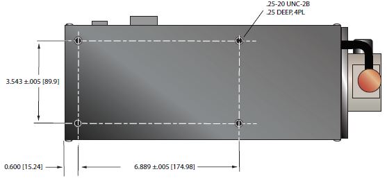
Mechanical:
See drawings
Weight:
Standard: 30lbs. (13.60kg)
Standard/Extended Tube: 34lbs. (15.40kg)
Light Weight (LW option): 23lbs. (10.43kg)
Light Weight/Extended Tube: 27lbs. (12.24kg)
Regulatory Approvals:
Compliant to EEC EMC Directive.
Compliant to EEC Low Voltage Directive.
J1 INPUT/OUTPUT—16 PIN AMP #206036-1 CONNECTOR
| Pin | Signal | Parameters |
|---|---|---|
| 1 | Chamber Interlock Out | To close Chamber Interlock connect pin 1 to pin 2, R<2Ω |
| 2 | Chamber Interlock In | To close Chamber Interlock connect pin 2 to pin 1, R<2Ω |
| 3 | X-Ray ON Lamp Out | 120Vac @ 3A/250Vac @ 1.5A rated contacts. Close at X-Ray ON |
| 4 | X-Ray ON Lamp In | 120Vac @ 3A/250Vac @ 1.5A rated contacts. Close at X-Ray ON |
| 5 | N/C | N/C |
| 6 | Prime Power Interlock Out | To close Power Interlock connect pin 6, 7 to pin 8, 10, R<2Ω |
| 7 | Prime Power Interlock Out | To close Power Interlock connect pin 6, 7 to pin , R<2Ω |
| 8 | Prime Power Interlock In | To close Power Interlock connect pin 8, 10 to pin 6, 7, R<2Ω |
| 9 | N/C | N/C |
| 10 | Prime Power Interlock In | To close Power Interlock connect pin 8, 10 to pin 6, 7, R<2Ω |
| 11 | +24Vdc Input (+) | +24Vdc Input (+) |
| 12 | +24Vdc Input (+) | +24Vdc Input (+) |
| 13 | +24Vdc Return (-) | +24Vdc Return (-) |
| 14 | +24Vdc Return (-) | +24Vdc Return (-) |
| 15 | X-Ray On Indicator Out | 24Vdc @ 3A rated contacts. Close at X-Ray On |
| 16 | X-Ray On Indicator In | 24Vdc @ 3A rated contacts. Close at X-Ray On |
J2 RS-232 DIGITAL INTERFACE—9 PIN AMP #788903-1 CONNECTOR
| Pin | Signal | Parameters |
|---|---|---|
| 1 | DCD | Data Carrier Detect |
| 2 | RD | Received Data |
| 3 | TD | Transmitted Data |
| 4 | DTR | Data Terminal Ready |
| 5 | SGNO | Signal Ground |
| 6 | DSR | Data Set Ready |
| 7 | RTS | Request to send |
| 8 | CTS | Clear to Send |
| 9 | RI | Ring Indicator |
SPOT TABLE
| PARAMETER | NARROW BEAM | WIDE BEAM |
|---|---|---|
| Operating Voltage Range | 45-130kV | 50-130kV |
| Maximum Power | 65W, 130kV | 65W, 130kV |
| Maximum Beam Current | 0.500mA | 0.500mA |
| Spot Size 4 Watt | ≤ 7μ, 45-130kV | ≤ 8μ, 50-130kV |
| Spot Size 8 Watt | ≤ 10μ, 45-130kV | ≤ 14μ, 50-130kV |
| Spot Size 16 Watt | ≤ 22μ, 45-130kV | ≤ 24μ, 50-130kV |
| Spot Size 32 Watt | ≤ 48μ, 70-130kV | ≤ 48μ, 70-130kV |
| Spot Size 40 Watt | ≤ 60μ, 80-130kV | ≤ 60μ, 80-130kV |
| Spot Size 65 Watt | ≤ 100μ, 130kV | ≤ 100μ, 130kV |
| How to Order: |
|---|
| Standard (Narrow Beam) PART NO.: μXRB130P65NB |
|
Wide Beam Option PART NO.: μXRB130P65WB |
Tables & Diagrams
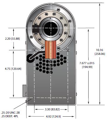
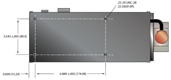
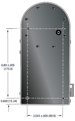
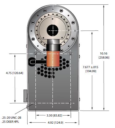
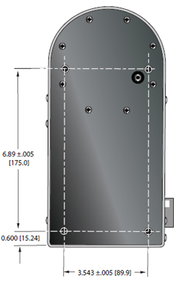
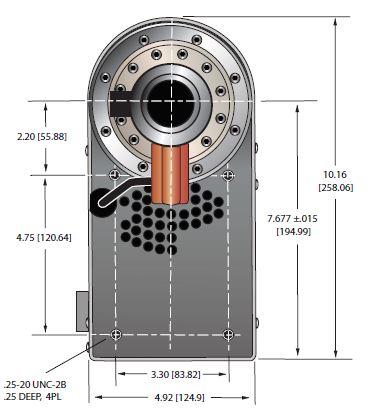
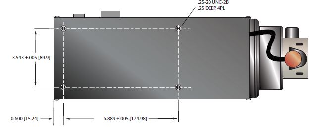
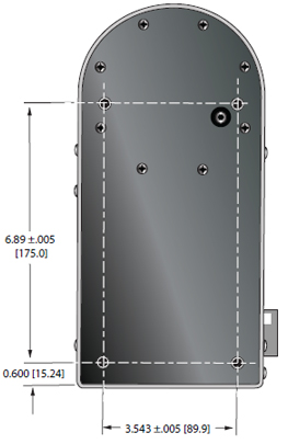
DIMENSIONS: in.[mm]
NARROW BEAM (Standard)
SIDE VIEW
BOTTOM VIEW
REAR VIEW
FRONT VIEW
DIMENSIONS: in.[mm]
WIDE BEAM (WB Option)
SIDE VIEW
BOTTOM VIEW
REAR VIEW
FRONT VIEW
DIMENSIONS: in.[mm]
WIDE BEAM (WB Option) and EXTENSION TUBE (ET Option)
BOTTOM VIEW
REAR VIEW
FRONT VIEW