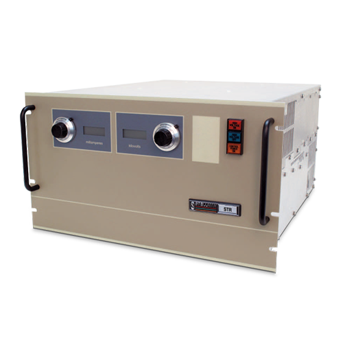
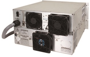
STRシリーズ
- シングル6U (10.5インチ) シャーシ
- モデル: 1kV~150kV
- リモートアナログ、リモートイーサネットインターフェイス
- アーク保護、短絡保護
- イーサネットインターフェイスでユーザー設定可能
- OEMカスタム化可能
*注: すべての仕様は予告なく変更される場合があります。最新版についてはこのデータシートの英語PDFをご覧ください。


6kW高電圧電源
スペルマンのSTRシリーズ6kW高電圧電源は正、負極性の19モデル、出力電圧は1kV~150kVでお届けしています。フロントパネルには豊富な機能を備えてローカルなコントロールが容易にでき、また充実したアナログインターフェイスには豊富なリモート機能があります。標準のイーサネットとRS-232デジタルインターフェイスで、STRはお使いのシステム設計への組み込みも簡単です。
STRのIGBTインバーターは丈夫で、本質的にフォールトトレラントですので、半導体プロセスや真空蒸着などの厳しい用途にも最適です。ユーザーは多くの操作機能を設定して、具体的な要件に適合させることができます。
典型的な用途:
- イオンビーム注入
- 半導体プロセス
- 電子ビーム溶接
- コンデンサ充電器
- 高電力RF送信機
- 静電集塵装置
- X線システム
デジタルインターフェイス
STRは標準のRS-232およびイーサネットデジタルインターフェイスを備えています。これらの標準デジタルインターフェイスを用いると、電源のインターフェイス要件を大幅に簡素化でき、ユーザーの時間と経費の両方を節約し、また機能と全体的な性能を向上できます。スペルマンはSTRにGUIを搭載し、STRの機能をカスタマイズし、基本的な電源操作機能も提供します。STRのデジタルインターフェイス機能は、このデータシートの1ページ目にあるリンクからダウンロードできるSTRマニュアルで詳説されています。
アーク介入
スペルマンのSTR電源にはアーク介入機能があり、高速電流検知変成器でアーク電流を検知します。アーク介入回路の目的は、連続的で長時間にわたるアークから電源を保護することです。出荷時デフォルトの設定では、10秒間にアークが4回発生すると装置がオフになります。基本的なアーク介入パラメーター (アーク数、アーク消去、再ランプ時間、ウィンドウ時間) はデジタルインターフェイスで予め設定された限度内で変更でき、またカスタマイズされた装置もお客様固有のアークに弱い環境に合わせて提供させていただきますので、詳細はスペルマンにお問い合わせください。
Specifications
(Ref. 128102-001 REV. L)
SPECIFICATIONS
Input Voltage:
Standard: 180-264Vac, 50/60Hz, three phase, 90% efficiency, 0.85 power factor
Optional: 360-528Vac 50/60Hz, three phase (400VAC) 180-264Vac 50/60Hz, single phase (1PH)
Input Current:
Standard: 180-264Vac, three phase 25 amps, maximum
Optional: 360-528Vac, three phase 12.5 amps, maximum 180-264Vac, single phase 57 amps, maximum
Output Voltage:
19 models from 1kV to 150kV. Each model is available with positive or negative outputs. 1kV to 10kV units are internally reversible.
Local Output Controls:
Voltage and current are continuously adjustable over entire range via ten-turn potentiometers with lockable counting dials.
Voltage Regulation:
Load: 0.05% of full voltage +500mV for full load change.
Line: 0.05%of full voltage +500mV over specified input range.
Current Regulation:
Load: 0.05% of full current ±100µA for any voltage change.
Line: 0.05% of full current over specified input range.
Ripple:
0.1% p-p +1Vrms
Stability:
0.02%hr. after 1 hour warm-up.
Temperature Coefficient:
100ppm/°C. Higher stability (50ppm/°C) available on special order via the HS option
Environmental:
Temperature Range:
Operating: 0°C to 40°C
Storage: -40°C to 85°C
Humidity:
10% to 90% RH, non-condensing.
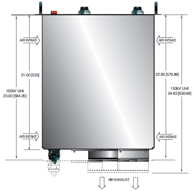
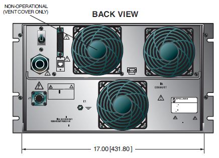
Cooling:
Forced air; inlet through side panels, outlet at rear panel
Metering:
Digital voltage and current meters, accurate to within 1%
System Status Display:
“Dead Front” type indicators provide status of up to 12 system operations including voltage and current regulation, fault conditions and circuit control.
Analog Interface Connector:
50 pin female D connector
High Voltage Output Cable:
A detachable 10’ (3.05m) long shielded HV cable is provided
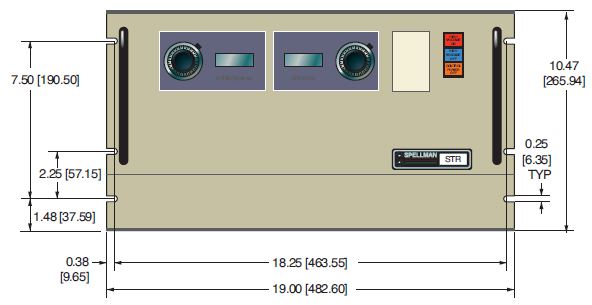
Dimensions:
1kV to 120kV:
10.5. (6U)H X 19. W X 21. D (266mm x 482mm x 533mm)
150kV:
10.5. (6U)H X 19. W X 23. D (266mm x 482mm x 584mm)
Weight:
1kV to 50kV: <100 pounds (45.36kg)
60kV to 120kV: <140 pounds (63.50kg)
150kV: <150 pounds (68kg)
Individual kV models may vary
Regulatory Approvals:
Designed to meet EEC EMC Directive. Compliant to EEC Low Voltage Directive. RoHS Compliant.
BFP - Blank Front Panel
HS - High Stability
LL(X) - High Voltage Cable Length
400VAC - 360-528Vac, Three Phase Input
1PH - 180-264Vac, Single Phase Input
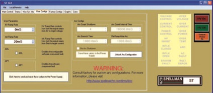
Software Configurable Features:
Adjustable Overload Trip Arc Trip Count Arc Quench Time Arc Re-Ramp Time Constant Power Control Adjustable Power Trip Slow Start Ramp Times
Digital Interface
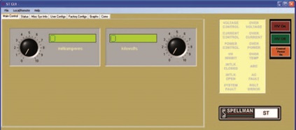
The STR features a standard RS-232 and Ethernet digital interface. Utilizing these standard digital interfaces can dramatically simplify power supply interfacing requirements saving the user both time and money, while enhancing functionality and overall capability. Spellman provides a GUI with the STR that allows the customer to both customize operational features of the STR while also providing basic power supply operational features.
Main control screen
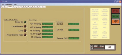
Status screen
User configuration screen
Arc Intervention
Spellman’s STR power supplies have an arc intervention feature that senses arc currents via a fast acting current sense transformer. The purpose of the arc intervention circuitry is to prevent power supply damage from continuous, long term arcing. The factory default configuration will trip off the unit with an Arc Fault if 4 arcs occur in a 10 second time period. Customers can change basic arc intervention parameters (Arc Count, Arc Quench, Reramp Time, and Window Time) within preset limits via the digital interface; customized units can be provided for unique arc prone environments, contact Spellman for details.
STR rear panel view
Electronic Component (Power Source)
STR series is intended for installation as a component of a system. It is designed to meet CE standards, with conditions of acceptance often being: customer provided enclosure mounting, EMC filtering, and appropriate protection, and isolation devices. The STR series is not intended to be operated by end users as a stand-alone device. The STR series power supply can only be fully assessed when installed within a system, and as a component part within that system.
STR SELECTION TABLE
| Maximum Rating | Model Number | |
|---|---|---|
| kV | mA | |
| 1 | 6,000 | STR1*6 |
| 2 | 3,000 | STR2*6 |
| 3 | 2,000 |
STR3*6 |
| 4 | 1,500 | STR4*6 |
| 6 | 1,000 | STR6*6 |
| 8 |
750 | STR8*6 |
| 10 | 600 | STR10*6 |
| 12 | 500 | STR12*6 |
| 15 | 400 | STR15*6 |
| 20 | 300 | STR20*6 |
| 30 | 200 | STR30*6 |
| 40 | 150 | STR40*6 |
| 50 | 120 | STR50*6 |
| 60 | 100 | STR60*6 |
| 70 | 86 | STR70*6 |
| 80 | 75 | STR80*6 |
| 100 | 60 | STR100*6 |
| 120 | 50 | STR120*6 |
| 150 |
40 | STR150*6 |
*Substitute “P” for positive polarity and “N” for negative polarity. Polarity must be specified at time of order.
1-10kV units are inherently reversible by design requiring an internal wiring change to swap polarities. Intermediate voltage units are available by special order.
JB1 STR ANALOG INTERFACE 50 PIN FEMALE D CONNECTOR
| Pin | Signal | Parameters |
|---|---|---|
| 1 | Power Supply Common | Power Supply Ground |
| 2 | Reset/HV Inhibit | Normally open, Low = Reset/Inhibit |
| 3 | External Interlock | +24Vdc @ open, <25mA @ closed |
| 4 | External Interlock Return | Return for External Interlock |
| 5 | mA Test Point | 0-10Vdc = 0-100% rated output, Zout= 1KΩ, 1% |
| 6 | kV Test Point | 0-10Vdc = 0-100% rated output, Zout= 1KΩ, 1% |
| 7 | +10Vdc Reference Output | +10Vdc @ 1mA |
| 8 | mA Program Input | 0-10Vdc = 0-100% rated output, Zin>10MΩ |
| 9 | Local mA Program Output | 0-10Vdc = 0-100% rated output, front panel pot |
| 10 | kV Program Input | 0-10Vdc = 0-100% rated output, Zin>10MΩ |
| 11 | Local kV Program Output | 0-10Vdc = 0-100% rated output, front panel pot |
| 12 | Remote Power On Output | +24Vdc @ open, 2A peak, 1Adc @ closed |
| 13 | Remote Power On Return | Return for Remote Power On |
| 14 | Remote HV Off | +24Vdc @ open, 2A peak, 1Adc @ closed, connect to pin15 for front panel operation |
| 15 | Remote HV Off/On Common | HV On/Off Common |
| 16 | Remote HV On | +24Vdc @ open, 2A peak, 1Adc @ closed, momentarily connect to pin 15 enable high voltage |
| 17 | HV Off Indicator | +24Vdc @ 25mA = HV Off |
| 16 | HV On Indicator | +24Vdc @ 25mA = HV On |
| 19 | Power Supply Common | Supply Ground |
| 20 | +24Vdc Output | +24Vdc @ 100mA, maximum |
| 21 | Voltage Mode Status | Open Collector, Low = Active |
| 22 | Current Mode Status | Open Collector, Low = Active |
| 23 | Power Mode Status | Open Collector, Low = Active |
| 24 | Interlock Closed Status | Open Collector, Low = Active |
| 25 | Power Test Point | 0-10Vdc = 0-100% rated output, Zout= 5KΩ, 1% |
| 26 | Spare | |
| 27 | Spare | |
| 28 | Remote Overvoltage Adjust | 0-10Vdc = 0-100% rated output |
| 29 | Over Power Fault | Open Collector, Low = Active |
| 30 | Over Voltage Fault | Open Collector, Low = Active |
| 31 | Over Current Fault | Open Collector, Low = Active |
| 32 | System Fault | Open Collector, Low = Active |
| 33 | RGLT Error Fault | Open Collector, Low = Active |
| 34 | Arc | Open Collector, Low = Active |
| 35 | Over Temp Fault | Open Collector, Low = Active |
| 36 | AC Fault | Open Collector, Low = Active |
| 37 | Spare | |
| 38 | Spare | |
| 39 | Spare | |
| 40 | Spare | |
| 41 | Spare | |
| 42 | Remote Power Program Input | 0-10Vdc = 0-100% rated output, Zin>10MΩ |
| 43 | Local Power Program Output | 0-10Vdc = 0-100% rated output, internal pot |
| 44 | +5Vdc Output | +5Vdc @ 100mA, maximum |
| 45 | +15Vdc Output | +15Vdc @ 100mA, maximum |
| 46 | -15Vdc Output | -15Vdc @ 10mA, maximum |
| 47 | RS232 Tx | |
| 48 | RS232 Rx | |
| 49 | RS232 GND | |
| 50 | Power Supply Common | Power Supply Ground |
Tables & Diagrams
DIMENSIONS: in.[mm]
FRONT VIEW
TOP VIEW
BACK VIEW
Frequently Asked Questions
What Is a Safe Level of High Voltage?
What Is an “External Interlock”?
Where Can I Obtain Information on High Voltage Safety Practices?
What Do You Mean That the Output Side of the High Voltage Cable on Most Standard Products Is “Unterminated”?
How Should I Ground Your Supply?
Why Is Arcing an Issue for a High Voltage Power Supply?
Application Notes AN-13 – Arc Intervention Circuitry and External Series Limiting Resistors
Application Notes AN-14 – The Limits of Front Panel Digital Meters
Application Notes AN-15 – 3.5 And 4.5 Digit Meter Displays Explained
Application Notes AN-18 – Current Loop/Arc Detection Circuitry
Application Notes AN-19 – High Voltage Cable Lengths Discussed

