XRB160PN192
- Fuente de alto voltaje integrada, fuente de filamento, tubo de rayos X, puerto de haz y electrónica de control
- Compacto y ligero
- Entrada universal, factor de potencia corregido
- Puede montarse en cualquier orientación física
- Monitorización analógica e interfaz digital estándar RS-232
Nota: Todas las especificaciones pueden cambiar sin previo aviso. Por favor, consulte la versión en PDF en inglés de esta hoja técnica para la revisión más actualizada.
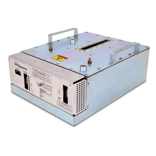
XRB160PN192 Monoblock® Industrial X-Ray Generators
El Monoblock® XRB160PN192 de Spellman fuente de rayos X está diseñada para aplicaciones OEM que alimenta su tubo interno de rayos X hasta 160kV a 192W. Características como la entrada universal, el tamaño pequeño y una interfaz analógica estándar y digital RS-232 simplifican la integración de este Monoblock® en tu sistema de rayos X. Los modelos estándar están disponibles con geometría de haz en forma de abanico. La circuitería propietaria de control de emisiones proporciona una excelente regulación de la corriente del tubo de rayos X, junto con un rendimiento de estabilidad sobresaliente.
APLICACIONES TÍPICAS
Escaneo de rayos X: medición de placas, inspección de alimentos, confirmación de niveles de llenado y aplicaciones de seguridad
Especificaciones
(Ref. 128085-001 REV. M)
X-Ray Characteristics:
Tube Type: Glass tube, Tungsten target, Be filter
Focal Spot: 0.8mm x 0.8mm
Beam Filter: 0.016˝ thick 6061 Al
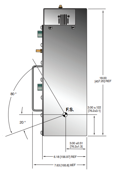
Beam Geometry: Asymmetrical fan 80° x 10° ±2°
Input Voltage:
100-240Vac ±10%, 50/60Hz, 5A maximum
X-Ray Tube Voltage:
0.1mA to 1.2mA, 192W maximum over specified tube voltage range
X-Ray Tube Power:
192W maximum continuous
Voltage Regulation:
Line: ±0.1% for a ±10% input line change of nominal input line voltage
Load: ±0.1% for a 0.1mA to 1.2mA load change
Voltage Accuracy:
Voltage measured across the X-Ray tube is within ±2% of the programmed value
Voltage Risetime:
Ramp time shall be <200ms from 10% to 90% of rated output
Voltage Overshoot:
Within 5% of rated voltage in <10ms
Voltage Ripple:
1% p p of rated voltage @ ≤1kHz
Current Regulation:
Line: ±0.1% for a ±10% input line change of nominal input line voltage
Load: 0.5% @ 80-160kV, 0.1mA to 1.2mA
Current Accuracy:
Current measured through the X-Ray tube is within ±2% of the programmed value
Current Risetime:
<200ms from 10% to 90% of rated output
Arc Intervention:
4 arcs in 10 seconds with a 200ms quench = Shutdown
Filament Configuration:
Internal high frequency AC filament drive with closed loop filament emission control
Analog Interface:
0 to 10Vdc ground referenced signals
Digital Interface:
RS-232 interface
Control Software:
A demo GUI for engineering evaluations will be provided for the RS-232 digital interface upon request.
Interlock Signals:
A hardware interlock function is provided
Operating Temperature:
0°C to +40°C
Storage Temperature:
-40°C to +70°C
Humidity:
10% to 95% relative humidity, non-condensing
Cooling:
Natural convection augmented by customer provided 250cfm cooling fans for 192W operation
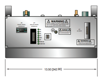
Input Line Connector:
6 pin Molex 26-60-4060
Analog Interface Connector:
7 pin Molex 26-60-5070
Digital Interface Connector:
9 pin D connector, female
Grounding Point:
8-32 ground stud provided on chassi
Dimensions:
18" x 13.5" x 7.63" (458mm x 343mm x 193.80mm)
Weight:
90lbs (40.5kg)
Orientation:
Can be mounted in any orientation.
X-Ray Leakage:
Not to be greater than 0.5mR/hr at 5cm outside the external surface
Regulatory Approvals:
Compliant to EEC EMC Directive (external EMC filter required). Compliant to EEC Low Voltage Directive. UL/CUL recognized file E235530.
AC INPUT POWER J1 6 PIN CONNECTOR
| Pin | Signal | Parameters |
|---|---|---|
| 1 | Line | Line |
| 2 | Removed | N/C |
| 3 | Neutral | Neutral |
| 4 | Removed | N/C |
| 5 | Spare | N/C |
| 6 | Spare | N/C |
TERFACE— J7 7 PIN MOLEX CONNECTOR
| Pin | Signal | Parameters |
|---|---|---|
| 1 | Ex Gate | Low = X-Ray OFF, +12Vdc = X-Ray ON |
| 2 | Signal Ground | Ground |
| 3 | N/C | No Connection |
| 4 | kV Monitor | 0-9 Vdc = 0 to 100% rated output |
| 5 | Signal Ground | Ground |
| 6 | mA Monitor | 0 to 9Vdc = 0 to 100% rated output |
| 7 | Fault | Open collector, 35V @ 10mA max, High = No Fault |
LED INDICATORS
| Pin | Signal | Parameters |
|---|---|---|
| LED 1 | OV | High kV occurs |
| LED 2 | UV | Low kV occurs |
| LED 3 | UC | Low mA occurs |
| LED 4 | OC | High mA occurs |
| LED 5 | ARC FLT | Arc fault occurs |
| LED 6 | OT | Over temperature occurs |
| LED 7 | X-RAY ON | X-Rays are enabled |
| LED 8 | PWR | Power is ON |
Tablas y Diagramas
DIMENSIONS: in.[mm
FRONT VIEW
TOP VIEW

BACK VIEW
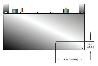
SIDE VIEW