SERIE XRB160PN192
- Fuente de alto voltaje con alimentación de filamento, tubo de rayos X, puerto de haz y electrónica de control integrados
- Compacta y ligera
- Entrada universal, factor de potencia corregido
- Se puede montar en cualquier orientación física
- Interfaz de monitoreo analógica e interfaz digital estándar RS-232
FUENTE DE RAYOS X DE 160 KV, 200 W
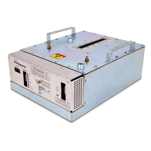
El generador de rayos X XRB160PN192 Monoblock® de Spellman está diseñado para aplicaciones OEM que alimentan su tubo de rayos X interno de hasta 160 kV a 192W. Características como la entrada universal, el tamaño pequeño, una interfaz analógica y RS-232 digital estándar simplifican la integración de este Monoblock® en su sistema de rayos X. Los modelos estándar están disponibles con geometría de haz en forma de abanico. Los circuitos patentados de control de emisiones proporcionan una excelente regulación de la corriente del tubo de rayos X, junto con un rendimiento de estabilidad excepcional.
Aplicaciones típicas:
- Barrido de rayos X: medición de chapados
- Inspección de alimentos
- Confirmación de nivel de llenado
- Aplicaciones de seguridad
![]()
Especificaciones
(Ref. 128082-001 REV. M)
X-Ray Characteristics:
Tube Type: Glass tube, Tungsten target, Be filter
Focal Spot: 0.8mm x 0.8mm.
Beam Filter: 0.016. thick 6061 Al.
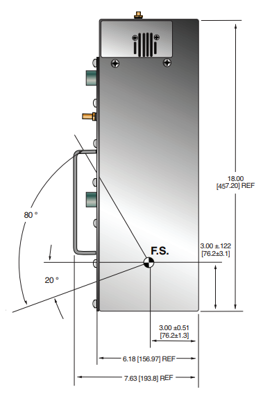
Beam Geometry: Asymmetrical fan 80° x 10° +/-2°
Input Voltage:
100-240Vac, 50/60Hz, 5A maximum +/-10%
X-Ray Tube Voltage:
Nominal X-Ray tube voltage is adjustable between 80kV to 160kV
X-Ray Tube Current:
0.1mA to 1.2mA, 192W maximum over specified tube voltage range
X-Ray Tube Power:
192W, maximum continuous
Voltage Regulation:
Line: ±0.1% for a ±10% input line change of nominal input line voltage Load: ±0.1% for a 0.1mA to 1.2mA load change
Voltage Accuracy:
Voltage measured across the X-Ray tube is within ±2% of the programmed value
Voltage Risetime:
Ramp time shall be <200ms from 10% to 90% of rated output
Voltage Overshoot:
Within 5% of rated voltage in <10ms
Voltage Ripple:
1% p p of rated voltage @ =1kHz
Current Regulation:
Line: ±0.1% for a ±10% input line change of nominal input line voltage
Load: 0.5% @ 80-160kV, 0.1mA to 1.2mA
Current Accuracy:
Current measured through the X-Ray tube is within ±2% of the programmed value
Current Risetime:
<200ms from 10% to 90% of rated output
Arc Intervention:
4 arcs in 10 seconds with a 200ms quench = Shutdown
Filament Configuration:
Internal high frequency AC filament drive with closed loop filament emission control
Analog Interface:
0 to 10Vdc ground referenced signals
Digital Interface:
RS-232 interface.
Control Software:
A demo GUI for engineering evaluations will be provided for the RS-232 digital interface upon request.
Interlock Signals:
A hardware interlock function is provided
Operating Temperature:
0°C to +40°C
Storage Temperature:
-40°C to +70°C
Humidity:
10% to 95% relative humidity, non-condensing
Cooling:
Natural convection augmented by customer provided 250cfm cooling fans for 192W operatio
Input Line Connector:
6 pin Molex 26-60-4060
Analog Interface Connector:
7 pin Molex 26-60-5070
Digital Interface Connector:
9 pin D connector, female
Grounding Point:
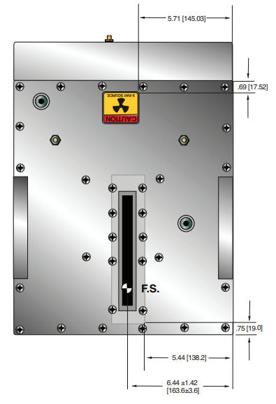
32 ground stud provided on chassis
Dimensions:
18" X 13.5" X 7.63" (458mm X 343mm X 193.80mm)
Weight:
90lbs (40.5kg)
Orientation:
Can be mounted in any orientation.
X-Ray Leakage:
Not to be greater than 0.5mR/hr at 5cm outside the external surface.
Regulatory Approvals:
Compliant to EEC EMC Directive (External EMC filter required). Compliant to EEC Low Voltage Directive. UL/CUL recognized file E235530.
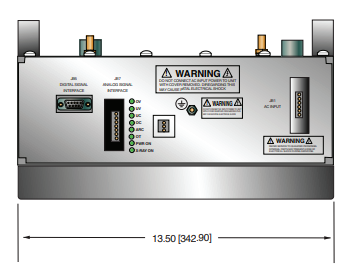
AC INPUT POWER J1 6 PIN CONNECTOR
| Pin | Signal | Parameters |
|---|---|---|
| 1 | Line | Line |
| 2 | Removed | N/C |
| 3 | Neutral | Neutral |
| 4 | Removed | N/C |
| 5 | Spare | N/C |
| 6 | Spare | N/C |
RS-232 DIGITAL INTERFACE— JB16 9 PIN FEMALE D CONNECTOR
| Pin | Signal | Parameters |
|---|---|---|
| 1 | N/C | No Connection |
| 2 | TD | Transmit Data |
| 3 | RD | Receive Data |
| 4 | N/C | No Connection |
| 5 | SGND | Signal Ground |
| 6 | N/C | No Connection |
| 7 | N/C | No Connection |
| 8 | N/C | No Connection |
| 9 | N/C | No Connection |
ANALOG INTERFACE— J7 7 PIN MOLEX CONNECTOR
| Pin | Signal | Parameters |
|---|---|---|
| 1 | Ex Gate | Low = X-Ray OFF, +12Vdc = X-Ray ON |
| 2 | Signal Ground | Ground |
| 3 | N/C | No Connection |
| 4 | kV Monitor | 0-9 Vdc = 0 to 100% rated output |
| 5 | Signal Ground | Ground |
| 6 | mA Monitor | 0 to 9Vdc = 0 to 100% rated output |
| 7 | Fault | Open collector, 35V @ 10mA max, High = No Fault |
LED INDICATORS
| Indicator | Signal Name | Condition Illuminated When... |
|---|---|---|
| LED 1 | OV | High kV occurs |
| LED 2 | UV | Low kV occurs |
| LED 3 | UC | Low mA occurs |
| LED 4 | OC | High mA occurs |
| LED 5 | ARC FLT | Arc fault occurs |
| LED 6 | OT | Over temperature occurs |
| LED 7 | X-RAY ON | X-Rays are enabled |
| LED 8 | PWR | Power is ON |
Tablas y Diagramas
DIMENSIONS: in.[mm]
FRONT VIEW
TOP VIEW
BACK VIEW
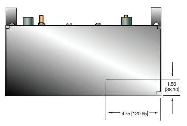
SIDE VIEW
Frequently Asked Questions
Why Is Oil Insulation Used?
Do I Need to Ensure My Monoblock® Stays Cool? Why?
How Often Do I Need to Season My Monoblock® X-Ray Source? Why?
Application Notes AN-12 – The Benefit of Using a Current Source to Power X-Ray Tube Filament Circuits