Интегрированный источник рентгеновского излучения XRBD Monoblock® СЕРИЯ
- Компактность и небольшая масса
- Универсальный вход, коррекция коэффициента мощности
- Возможность монтажа с любой ориентацией в пространстве
- Аналоговый интерфейс контроля, стандартный цифровой интерфейс RS-232 и интерфейс Ethernet
- Прогрев рентгеновской трубки с регистрацией данных и управлением с помощью микропрограммного обеспечения
*Примечание. Любые технические характеристики могут быть изменены без уведомления. Актуальное техническое описание приведено в PDF файле на английском языке.
ИСТОЧНИК РЕНТГЕНОВСКОГО ИЗЛУЧЕНИЯ 100 ВТ, 210 ВТ, 350 ВТ И 500 ВТ
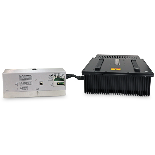
Изделия компании Spellman серии XRBD, входящие в семейство моноблочных рентгеновских источников Monoblock®, предназначены для применения в комплектном оборудовании. Они обеспечивают питание внутренних биполярных рентгеновских трубок напряжением до 160 кВ при уровнях мощности 100 Вт, 210 Вт, 350 Вт и 500 Вт. Универсальный вход питания, компактность и стандартный цифровой интерфейс RS-232 упрощают интеграцию XRBD в вашу систему рентгеновского излучения. Все модели XRBD поставляются с веерной (стандартное исполнение) или конической (опция) геометрией луча. Патентованная схема управления излучением обеспечивает высокую точность регулирования силы тока, подаваемого на рентгеновскую трубку, и непревзойденную стабильность рабочих характеристик.
СТАНДАРТНЫЕ ОБЛАСТИ ПРИМЕНЕНИЯ
Системы контроля качества пищевых продуктов, контроля уровня заполнения емкостей, сканирования с целью проверки безопасности, промышленного неразрушающего контроля, измерения толщины (в том числе металлических покрытий).
Технические характеристики
(Ref. 128132-001 REV. L)
Options:
CB Cone Beam
.5mm Beam Filter:
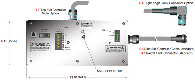
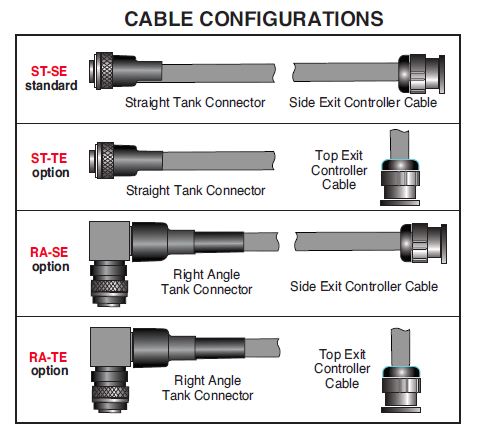
ST-TE, RA-SE, RA-TE See page 4 for Cable Options.
SPECIFICATIONS
X-Ray Characteristics:
Focal Spot: 0.8mm (IEC 336)
0.5mm (IEC 336) optional
Beam Filter:
Ultem: 1.50mm ±0.15mm
Oil: 9.0mm ±0.25mm
Glass: 1.7mm ±0.2mm
Be: 0.8mm
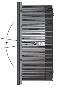
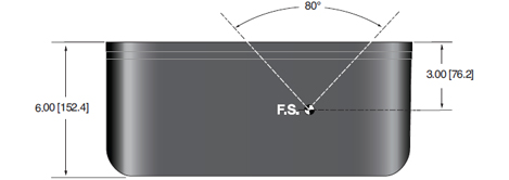
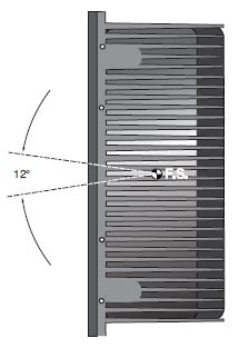
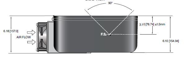
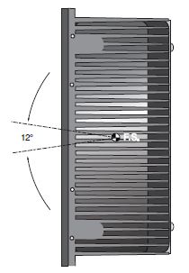
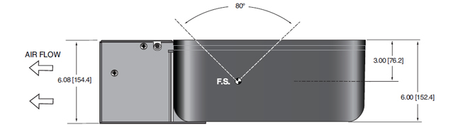
Beam Geometry:
Fan: Standard. The beam angular coverage will be 80° with the beam plane perpendicular to the X-Ray tube axis and 12° wide (with a 2° tolerance)
Cone: Optional. 40° cone beam (with a 2° tolerance)
Input Voltage:
100-240Vac, ±10%, 50/60 Hertz, .98 power factor
Input Current:
100W @ 1.4A
210W @ 2.8A
350W @ 4.6A
500W @ 6.6A
X-Ray Tube Voltage:
See table. Minimum kV for emission current 35kV
X-Ray Tube Current:
See table. Minimum emission current 150uA
X-Ray Tube Power:
See table
Voltage Regulation:
Line: ±0.05% of maximum output voltage over a ±10% change of nominal input line voltage
Load: ±0.1% of maximum rated voltage for 150uA to full rated load change
Voltage Accuracy:
Voltage measured across the X-Ray tube is within ±2% of the programmed value
Voltage Risetime:
Standard ramp time shall be <500ms from 10% to 90% of maximum rated output voltage
Voltage Ripple:
0.5% peak to peak of maximum voltage for frequencies ≤1kHz
Emission Current Parameters
Current Regulation:
Line: ±0.05% of rated output current over a ±10% change of nominal input line voltage
Load: ±0.1% of rated output current for a change from 50% to 100% of rated output voltage
Current Accuracy:
Current measured through the X-Ray tube is within ±2% of the programmed value
Current Risetime:
Standard: Ramp time shall be <500ms from 10% to 90% of maximum rated current
Arc Intervention:
4 arcs in 10 seconds with a 100ms quench/100ms re-ramp = Shutdown
Filament Configuration:
Internal AC filament drive with closed loop filament emission control
Analog Interface:
Ground referenced 0 to 9Vdc for all monitoring signals.
Relay contacts and open collector signals for other signals. See analog interface connector pin out table.
Digital Interface:
The RS-232 interface allows for programming of kV, mA output and X-Ray enable. Provides monitoring for kV, mA output and oil temperature. Tolerance 3%. (with an additional 5μA offset at ≤10% mA programming)
Operating Temperature:
0°C to +40°C
Storage Temperature:
-40°C to +70°C
Humidity:
10% to 95% relative humidity, non-condensing
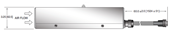
Cooling:
X-Ray Tank:
100W: Convection/customer supplied forced air so tank is < 55˚C
210W: Externally powered forced air cooling, 24Vdc @ 2A
350W/500W: Externally powered forced air cooling with oil pump and heat exchanger, 24Vdc @ 5A
Controller: Forced air via internal fan.
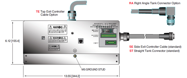
Grounding Point:
M5 ground female thread on tank
M5 ground stud on control chassis provided
Dimensions:
See drawings
Weight:
X-Ray Tank:
100W/210W @ 78 lbs. (35.4kg)
350W/500W @ 84.5lbs. (38.3kg)
Controller:
100W/210W: 4 pounds (1.18kg)
350W/500W: 7 pounds (3.18kg)
Orientation:
Can be mounted in any orientation.
X-Ray Leakage:
Not to be greater than 0.5mR/hr at 5cm outside the external surface.
Regulatory Approvals:
Compliant to EEC EMC Directive. Compliant to EEC Low Voltage Directive. UL/CUL recognized file E235530.
MODEL SELECTION TABLE
| Model | Maximum Voltage | Maximum Current | Maximum Power |
|---|---|---|---|
| XRBD160PN100 | 160kV | 1mA | 100 watts |
| XRBD160PN210 | 160kV | 2.1mA | 210 watts |
| XRBD160PN350 | 160kV | 3.5mA | 350 watts |
| XRBD160PN500 | 160kV | 4mA | 500 watts |
LED INDICATORS
| INDICATOR | SIGNAL | CONDITION Illuminated When... | LED COLOR |
|---|---|---|---|
| 1 | OV Error 6 | High kV occurs | Red |
| 2 | UV Error 5 | Low kV occurs | Red |
| 3 | UC Error 4 | Low mA occurs | Red |
| 4 | OC Error 3 | High mA occurs | Red |
| 5 | ARC Error 2 | Arc fault occurs | Red |
| 6 | OT Error 1 | Over temperature occurs | Red |
| 7 | X-Ray On | X-Rays are being generated | Green |
| 8 | Power On | AC input power is present | Green |
| SMART XRB |
|---|
|
The XRBD has two new digital features: data logging and firmware controlled seasoning. Data Logging: Think of this as an “airplane black box”. The data logging captures data on fault events and non-fault events. Fault events will turn off the high voltage: FAULT EVENTS Temperature The XRBD stores data 620ms before the event, the event itself and for 620ms after the event. Data is recorded every 20ms (62 samples total) showing: Anode kV We also log non-fault events, these are changes in set points or state of the unit. NON FAULT EVENTS HV On Fault event data is actual graphical data. Non fault event data is just stored as event type, data and timestamp. We also have a preventative maintenance fault, which throws a non-shutdown fault if the X-Ray tube has been factory installed over 4 years ago or if over 15,000 hours of HV ON is logged. Firmware Controlled Seasoning: Every unit comes with an initial seasoning table, or customers can set their own. The XRBD knows when the unit has been on, when it has been off, hours on the X-Ray tube, etc. As a preventative maintenance feature upon turn on, we review the data and suggest that a particular seasoning protocol be run based upon the actual usage history of the unit. Proper seasoning compliance of the X-Ray tube will help get the longest lifetime. |
Power and Interface Connections
AC INPUT—3 PIN PHOENIX1858772
| SIGNAL | PIN | PARAMETERS |
|---|---|---|
| 1 | AC Input (high) | 100-240Vac (high) |
| 2 | Ground | Ground |
| 3 | AC Input (neutral) | 100-240Vac (neutral) |
DC INPUT FOR HEAT DISSIPATION UNIT—4 PIN AMP (210/350/500W) 206060-1
| PIN | SIGNAL | DESCRIPTION | PARAMETERS |
|---|---|---|---|
| 1 | 24Vdc | Fan/Pump Power | 24Vdc @ 5 amps |
| 2 | 24Vdc Return | Fan/Pump Power | 24Vdc @ 5 amps |
| 3 | NC | No Connections | N/C |
| 4 | NC | No Connections | N/C |
It is critical to ensure that 24Vdc is supplied to pins 1 and 2
ANALOG INTERFACE— 10 PIN PHOENIX CONTACT 1792605
| PIN | SIGNAL | PARAMETERS |
|---|---|---|
|
1 |
X-Ray Interlock Enable | Apply +24Vdc to enable interlock. Open/removal of +24Vdc will cause X-Ray generation to stop. |
| 2 | X-Ray Interlock Enable Return | Ground reference for X-Ray Interlock. |
| 3 | Pin removed | N/C |
| 4 | kV Monitor | 0-10Vdc = 0-100% rated output voltage. Zout = 10kΩ |
| 5 | Signal Ground | Signal Ground |
| 6 | mA Monitor | 0-10Vdc = 0-100% rated output current. Zout =10kΩ |
| 7 | Fault Signal | Open collector, High (Open) = No Fault, 35Vdc @ 10mA maximum |
| 8 | HV ON Lamp Relay N/O | N/O dry contacts. 50 volts maximum. Rated for 1 amp or less, 50mA nominal load |
| 9 | HV ON Lamp Relay C | Common dry contacts. 50 volts maximum. Rated for 1 amp or less, 50mA nominal load |
| 10 | HV ON Lamp Relay N/C | N/C dry contacts. 50 volts maximum. Rated for 1 amp or less, 50mA nominal load |
RS-232 DIGITAL INTERFACE— 9 PIN MALE D CONNECTOR
| PIN | SIGNAL | PARAMETERS |
|---|---|---|
| 1 | N/C | N/C |
| 2 | Transmitted Data | Conforms to EIA RS-232-C |
| 3 | Received Data | Conforms to EIA RS-232-C |
| 4 | N/C | N/C |
| 5 | Signal Ground | Signal Ground |
| 6 | N/C | N/C |
| 7 | N/C | N/C |
| 8 | N/C | N/C |
| 9 | N/C | N/C |
ETHERNET DIGITAL INTERFACE— RJ45 8 PIN FEMALE CONNECTOR
| PIN | SIGNAL | PARAMETERS |
|---|---|---|
| 1 | TX + | Transmit Data + |
| 2 | TX - | Transmit Data - |
| 3 | RX + | Receive Data + |
| 4 | N/C | No Connection |
| 5 | N/C | No Connection |
| 6 | N/C | Receive Data - |
| 7 | N/C | No Connection |
| 8 | N/C | No Connection |
Таблицы и диаграммы
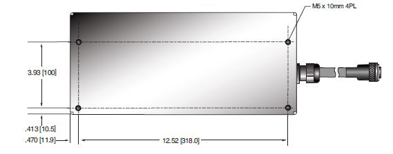
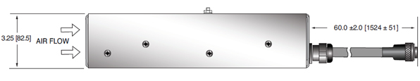
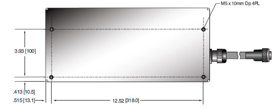
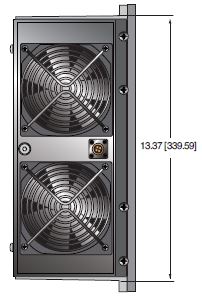
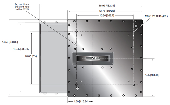
DIMENSIONS: in.[mm]
100/210W
CONTROL UNIT
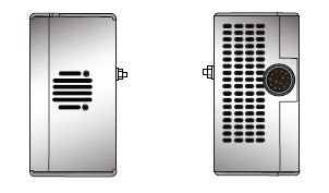
FRONTVIEW
BOTTOM VIEW
REAR VIEW
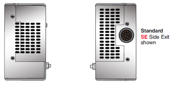
SIDE VIEW
DIMENSIONS: in.[mm]
300/500W CONTROL UNIT
FRONT VIEW
BOTTOM VIEW
REAR VIEW
SIDE VIEW
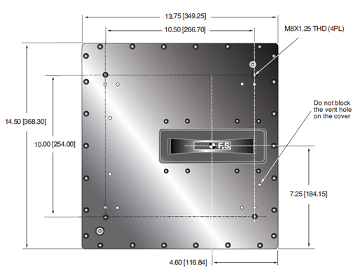
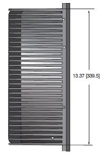
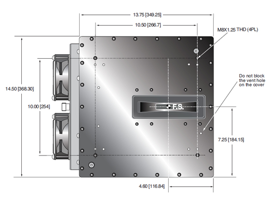
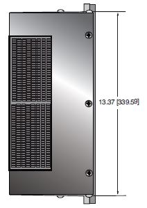
DIMENSIONS: in.[mm]
100W TANK
TOP VIEW
SIDE VIEW
BACK VIEW
FRONT VIEW
DIMENSIONS: in.[mm]
210W TANK
TOP VIEW
SIDE VIEW
BACK VIEW
FRONT VIEW
DIMENSIONS: in.[mm]
350/500W TANK
TOP VIEW
SIDE VIEW
BACK VIEW
FRONT VIEW