XRBe80PN300 Monoblock® 一体型X線源
- 小型・軽量
- ユニバーサル入力・力率補正
- あらゆる方向に取り付け可能
- アナログモニタリングインターフェース、標準RS-232デジタルインターフェース、イーサネット
- データロギングとファームウエア制御によるX線管シーズニング
*注:すべての仕様は予告なく変更される場合があります。 最新版については、このデータシートの 英語版PDF を参照してください。
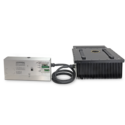
80KV/300W Be Window Monoblock®
スペルマンのXRBe80PN300ベリリウムウインドウMonoblock®X線源は、300Wの出力レベルで80kVのバイポーラX線管に電源を供給するOEMアプリケーション用に設計されています。ユニバーサル入力、コンパクトなパッケージサイズ、標準RS-232デジタルインターフェースなどの特長により、XRBe80PN300のX線システムへの統合が容易になります。円錐形のビーム形状もございます。独自のエミッション・コントロール回路により、X線管電流の優れたレギュレーションと優れた安定性を実現します。
代表的なアプリケーション
食品検査システム、充填レベル確認システム、セキュリティ・スキャニング・システム、工業用NDTシステム、厚さ/メッキ測定システム
Specifications
(Ref. 128132-001 REV. C)
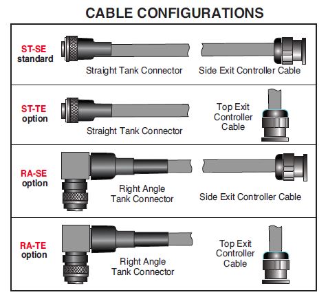
Options:
ST-TE, RA-SE, RA-TE Cable Options (see page 3 of the data sheet)
SPECIFICATIONS
X-Ray Characteristics:
Focal Spot: 0.8mm (IEC 336) standard
Beam Filter: Be 0.8mm
Beam Geometry:
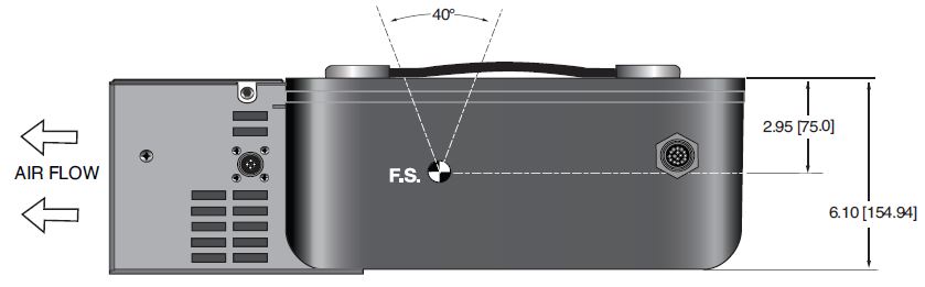
Cone: Standard. The beam angular coverage will be 40° with the beam plane perpendicular to the X-Ray tube axis
Input Voltage:
100- 240Vac, ±10%, 50/60 Hertz, .98 power factor
Input Current:
300W @ 6A
X-Ray Tube Voltage:
Maximum 80kV
X-Ray Tube Current:
Maximum 5mA
X-Ray Tube Power:
300W
Voltage Regulation:
Line: Line:±0.05% of maximum output voltage over a ±10% change of nominal input line voltage
Load: ±0.1% of maximum rated voltage for 150uA to full rated load change
Voltage Accuracy:
Voltage measured across the X-Ray tube is within ±2% of the programmed value
Voltage Risetime:
Standard ramp time shall be <500ms from 10% to 90% of maximum rated output voltage
Voltage Ripple:
0.5% peak to peak of maximum voltage forfrequencies ≤1kHz
X-Ray Tube Voltage:
Maximum 80kV
Emission Current Parameters
Current Regulation:
Line: ±0.05% of rated output current over a ±10% change of nominal input line voltage
Load: ±0.1% of rated output current for a change from 50% to 100% of rated output voltage
Current Risetime:
Standard ramp time shall be <500ms from 10% to 90% of maximum rated current
Arc Intervention:
4 arcs in 10 seconds with a 100ms quench/100ms re-ramp = Shutdown
Filament Configuration:
Internal floating AC filament drive with closed loop filament emission control circuitry
Analog Interface:
Ground referenced 0 to 9Vdc for all monitoring signals. Relay contacts and open collector signals for other signals. See analog interface connector pinout table.
Digital Interface:
The RS-232 interface allows for programming of kV, mA output and X-Ray enable. Provides monitoring for kV, mA output and oil temperature.
Operating Temperature:
0°C to +40°C
Storage Temperature:
-40°C to +70°C
Humidity:
10% to 95% relative humidity, non-condensing
Cooling:
X-Ray Tank: Externally powered forced air cooling with oil pump and heat exchanger, 24Vdc @ 5A
Controller: Forced air via internal fan.
Grounding Point:
M5 ground female thread on tank
M5 ground stud on control chassis provided
Dimensions:
X-Ray Tank: See drawings
Controller: See drawings
Weight:
X-Ray Tank:
81.5 lbs. (37kg)
Controller:
7 lbs. (3.18kg)
Orientation:
Can be mounted in any orientation.
X-Ray Leakage:
Not to be greater than 0.5mR/hr at 5cm outside the external surface.
Regulatory Approvals:
Compliant to EEC EMC Directive. Compliant to EEC Low Voltage Directive. UL/CUL recognized file E235530.
AC INPUT—3 PIN PHOENIX CONTACT 1858772
| PIN | SIGNAL | PARAMETERS |
|---|---|---|
| 1 | AC Input (high) | 100-240Vac (high) |
| 2 | Ground | Ground |
| 3 | AC Input (neutral) | 100-240Vac (neutral) |
DC INPUT FOR HEAT DISSIPATION UNIT—4 PIN AMP(210/350/500W) 206060-1
| PIN | SIGNAL | DESCRIPTION | PARAMETERS |
|---|---|---|---|
| 1 | 24Vdc | Fan/Pump Power | 24Vdc @ 5 amps |
| 2 | 24Vdc Return | Fan/Pump Power |
24Vdc @ 5 amp s |
| 3 | N/C | No Connection | N/C |
| 4 | N/C | No Connection | N/C |
It is critical to ensure that 24Vdc is supplied to pins 1 and 2
LED INDICATORS
| INDICATOR | SIGNAL | CONDITION Illuminated When... | LED COLOR |
|---|---|---|---|
| 1 | OV Error 6 | High kV occurs | Red |
| 2 | UV Error 5 | Low kV occurs | Red |
| 3 | UC Error 4 | Low mA occurs | Red |
| 4 | OC Error 3 | High mA occurs | Red |
| 5 | ARC Error 2 | Arc fault occurs | Red |
| 6 | OT Error 1 | Over temperature occurs | Red |
| 7 | X-Ray On | X-Rays are being generated | Green |
| 8 | Power On | AC input power is present | Green |
ANALOG INTERFACE—10 PIN PHOENIX CONTACT 1792605
| PIN | SIGNAL | PARAMETERS |
|---|---|---|
| 1 | X-Ray Interlock Enable | Apply +24Vdc to enable interlock. Open/removal of +24Vdc will cause X-Ray generation to stop. |
| 2 | X-Ray Interlock Enable Return | Ground reference for X-Ray Interlock. |
| 3 | Pin Removed | N/C |
| 4 | kV Monitor | 0-10Vdc = 0-100% rated output voltage. Zout = 10kΩ |
| 5 | Signal Ground | Signal Ground |
| 6 | mA Monitor | 0-10Vdc = 0-100% rated output current. Zout =10kΩ |
| 7 | Fault Signal | Open collector, High (Open) = No Fault, 35Vdc @ 10mA maximum |
| 8 | HV ON Lamp Relay N/O | N/O dry contacts. 50 volts maximum. Rated for 1 amp or less, 50mA nominal load |
| 9 | HV ON Lamp Relay C | Common dry contacts. 50 volts maximum. Rated for 1 amp or less, 50mA nominal load |
| 10 | HV ON Lamp Relay N/C | N/C dry contacts. 50 volts maximum. Rated for 1 amp or less, 50mA nominal load |
RS-232 DIGITAL INTERFACE—9 PIN MALE D CONNECTOR
| PIN | SIGNAL | PARAMETERS |
|---|---|---|
| 1 | N/C | N/C |
| 2 | Transmitted Data | Conforms to EIA RS-232-C |
| 3 | Received Data | Conforms to EIA RS-232-C |
| 4 | N/C | N/C |
| 5 | Signal Ground | Signal Ground |
| 6 | N/C | N/C |
| 7 | N/C | N/C |
| 8 | N/C | N/C |
| 9 | N/C | N/C |
ETHERNET DIGITAL INTERFACE—RJ45 8 PIN FEMALE CONNECTOR
| PIN | SIGNAL | PARAMETERS |
|---|---|---|
| 1 | TX+ | Transmit Data + |
| 2 | TX- | Transmit Data- |
| 3 | RX+ | Receive Data + |
| 4 | N/C | No Connection |
| 5 | N/C | No Connection |
| 6 | RX- | Receive Data - |
| 7 | N/C | No Connection |
| 8 | N/C | No Connection |
| SMART XRB |
|---|
|
The XRBD has two new digital features: data logging and firmware controlled seasoning. Data Logging: Think of this as an “airplane black box”. The data logging captures data on fault events and non-fault events. Fault events will turn off the high voltage: FAULT EVENTS Temperature The XRBe80PN300 stores data 620ms before the event, the event itself and for 620ms after the event. Data is recorded every 20ms (62 samples total) showing: Anode kV We also log non-fault events, these are changes in set points or state of the unit. NON FAULT EVENTS HV On Fault event data is actual graphical data. Non fault event data is just stored as event type, data and timestamp. We also have a preventative maintenance fault, which throws a non-shutdown fault if the X-Ray tube has been factory installed over 4 years ago or if over 15,000 hours of HV ON is logged. Firmware Controlled Seasoning: Every unit comes with an initial seasoning table, or customers can set their own. The XRBe80PN300 knows when the unit has been on, when it has been off, hours on the X-Ray tube, etc. As a preventative maintenance feature upon turn on, we review the data and suggest that a particular seasoning protocol be run based upon the actual usage history of the unit. Proper seasoning compliance of the X-Ray tube will help get the longest lifetime. |
Tables & Diagrams
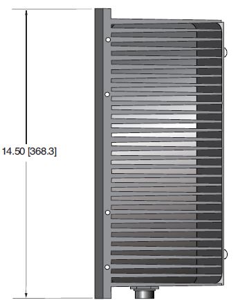
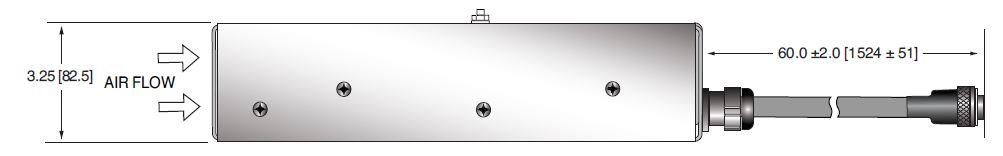
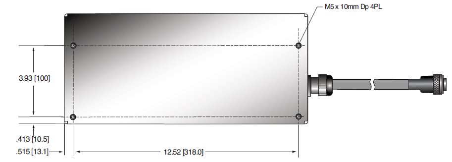
DIMENSIONS: in.[mm]
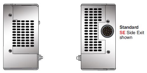
CONTROL UNIT
FRONTVIEW
BOTTOM VIEW
REAR VIEW
SIDE VIEW
DIMENSIONS: in.[mm]
TOP VIEW
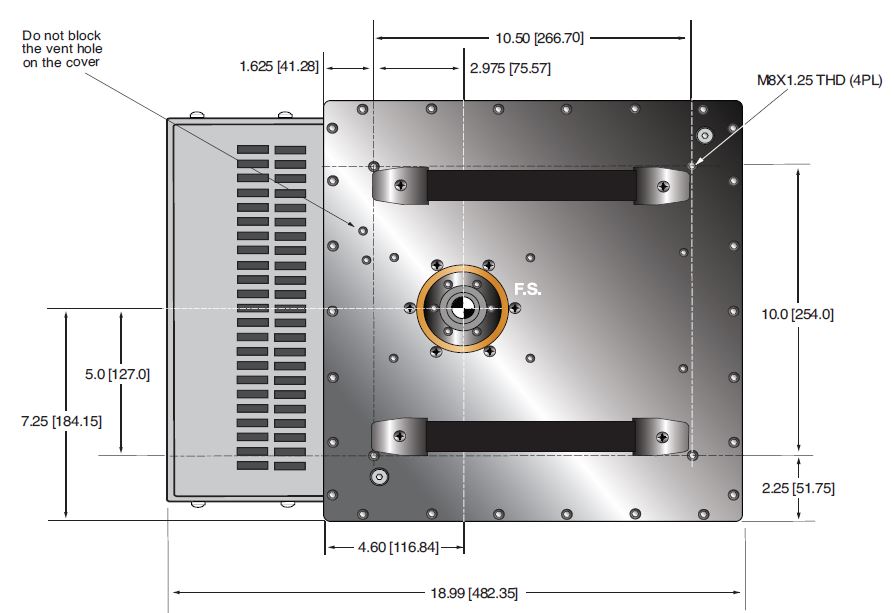
SIDE VIEW
FRONT VIEW