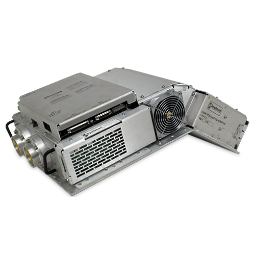
CT X線ジェネレーター
スペルマンは、30年以上にわたりOEMのお客様向けにCTジェネレーターを設計、製造してきました。1985年に連続回転CTスキャナーに使用されている、CTジェネレーターの最初のプロバイダーとなってから積み重ねてきた、豊富な経験を持っています。それ以来、スペルマンは性能を向上させ、毎年新しい製品を開発し、CTジェネレーター技術の標準を確立しました。
スペルマンのCTジェネレーターのCCTシリーズは、パフォーマンスと価格で独自の組み合わせをご提供いたします。 16スライスCTスキャナーに最適なこのジェネレーターは、32 kWから50 kWまでスケーリングできます。コンパクトなサイズと独自の折れ曲がった形状により、設置面積の小さいガントリー設計に適しています。 多くの既製のCTチューブと簡単にペアリングできるように設計されています。
Specifications
(Ref. 128125-001 REV. A)
OPTIONS
DG: Deflection Grid
CG: Cutoff Grid
SPECIFICATIONS
Input Voltage:
Main: 400Vac, three phase, +15%/-20%, 50/60Hz
Auxiliary: 220/230Vac, single phase, +15%/-10%, 50/60Hz
Output Voltage:
Range: 60kV to 140kV (bipolar, 30kV to 70KV)
Accuracy: ±0.5% of setting
Output Current:
Range: 10mA to 420mA, 50kW maximum.
10mA to 420mA, 50kW maximum.
10mA to 420mA, 50kW maximum.
Filament Output:
Auto reversible via front panel switch
Output Current:
Type: Two filament outputs, large and small
Voltage/Current: 15Vac (30kHz-40kHz) @ 0-6A maximum, referenced to cathode output
Power:
Maximum mA: 420mA, 50kW maximumMaximum kV: 140kV, 50kW maximum
Peak: 50kW
Maximum mA: 350mA, 42kW maximum
Maximum kV: 140kV, 42kW maximum
Peak: 42kW
Maximum mA: 275mA, 32kW maximum
Maximum kV: 140kV, 32kW maximum
Peak: 32kW
Gantry Rotation:
0.5 seconds
Starter:
Type: Dual Speed Starter
Compatibility: All industry standard X-Ray tubes
GRID SPECIFICATIONS
Deflection Grid: The deflection grid (also called the Flying Focal Spot) allows for dynamic movement of the focal spot providing double X sampling which increases effective resolution while decreasing unwanted artifacts.
Type: Deflection grid, single box assembly
Input Power: 24Vdc, ±10% @ 4.2A maximum, negative input ties to chassis ground internally
Connectors:
High Voltage Input: 3 pin 75kV Federal Standard (Cathode, Large, Small)
High Voltage Output: 4 pin 75kV CA7 (Cathode, Large, G1, G2)
Number of Grids: 2 grids, switching out of phase Bandwidth: DC to 5kHz
Output Voltage: 0V to -4KV, from grid to cathode. User input will command the bi-level grids to switch between adjustable voltages, VLOW and VHI. The two grids switch out of phase: If G1 is at VLOW, G2 will be at VHI and vice versa. The VLOW and VHI levels for G1 and G2 are independently adjustable from 0 to -4KV but VLOW range is constrained by: |VLOW | ≤ | VHI |
Cutoff Grid:
A cutoff grid truncates the high voltage at the end of the X-Ray exposure, reducing patient radiation dosing that does not contribute to the imaging process.
Type: Cutoff grid, single box assembly Input Power: 24Vdc, ±10% @ 0.75A maximum, negative input ties to chassis ground internally
Connectors:
High Voltage Input:
3 pin 75kV Federal Standard (Cathode, Large, Small)
High Voltage Output:
4 pin 75kV CA7 (Cathode, Large, G1, G2)
Number of Grids:
One, switched between “Zero” (0V≥Vg-c ZERO ≥ -10V) and “Cutoff” (Vg-c CUTOFF = -4kV±10% @ steady state)
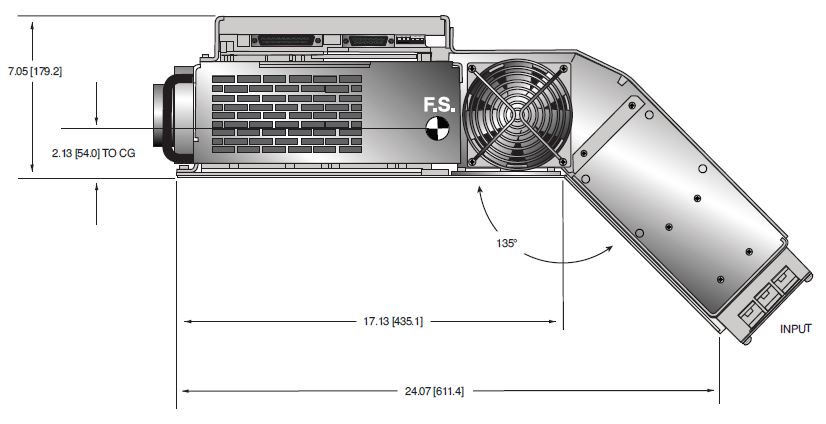
CCT X-RAY GENERATOR
DIMENSIONS: in.[mm]
TOP VIEW
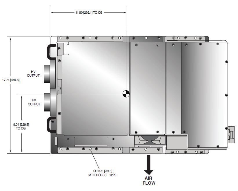
SIDE VIEW
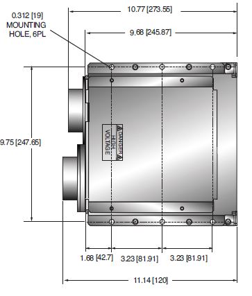
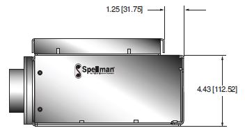
DEFLECTION / CUTOFF GRID
DIMENSIONS: in.[mm]
TOP VIEW
SIDE VIEW
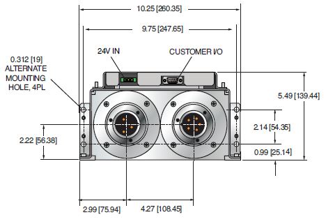
FRONT VIEW
Tables & Diagrams
| How to Order: | |
|---|---|
| 32kW maximum: | PART NO.: CCT70PN32 |
| 42kW maximum: | PART NO.: CCT70PN42 |
| 50kW maximum: | PART NO.: CCT70PN50 |
Consult sales for grid options
Frequently Asked Questions
Application Notes AN-12 – The Benefit of Using a Current Source to Power X-Ray Tube Filament Circuits
Application Notes AN-01 – Fundamentals of X-Ray Generator – X-Ray Tube Optimization

