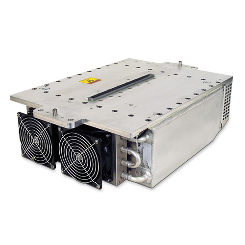
SERIE XRB160PN480/CT
- Fuente de alto voltaje con alimentación de filamento, tubo de rayos X, puerto de haz y electrónica de control integrados
- Compacta y ligera
- Se puede montar en cualquier orientación física
- Interfaz digital estándar RS-232
FUENTE DE RAYOS X DE 160 KV, 480 W
El generador de Rayos X XRB160PN480/CT Monoblock® de Spellman está diseñado para aplicaciones OEM que alimentan su tubo de rayos X interno de hasta 160 kV a 480 W. Características como el tamaño pequeño del paquete y la interfaz RS-232 digital simplifican la integración de este Monoblock® en su sistema de rayos X. Los modelos estándar están disponibles con geometría de haz en forma de abanico. Los circuitos de control de emisiones patentados proporcionan una excelente regulación de la corriente del tubo de rayos X, junto con un rendimiento de estabilidad excepcional.
Aplicaciones típicas:
- Barrido con rayos X: inspección de alimentos
- Confirmación de nivel de llenado
- Aplicaciones de seguridad
![]()
Especificaciones
(Ref. 128083-001 REV. J)
X-Ray Characteristics:
Tube Type: Glass tube, Tungsten target, Be filter
Focal Spot: 0.8mm x 0.8mm (IEC336)
Beam Filter: 1.75mm of glass, 1mm of Al, and 10mm of oil
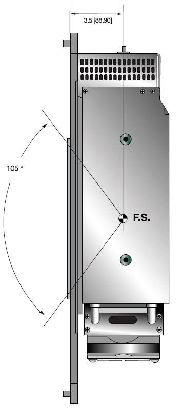
Beam Geometry: Symmetrical fan 105° ±3° x 4° ±1°
Input Voltage:
Monoblock®: 100-240Vac ±10%, 50/60Hz, 6.5A max
Heat Dissipation Unit: 24Vdc, 3A
X-Ray Tube Voltage:
Nominal X-Ray tube voltage is adjustable between 20kV to 160kV
X-Ray Tube Current:
0.3mA to 6mA over specified tube voltage range
X-Ray Tube Power:
320W continuous, 480W peak
Voltage Regulation:
Line: ±0.1% for a ±10% input line change of nominal input line voltage
Load: ±0.1% for a 0.3mA to 6mA load change
Voltage Accuracy:
Voltage measured across the X-Ray tube is within ±1% of the programmed value
Voltage Risetime:
Ramp time shall be <1 second from 1% to 90% of rated output
Voltage Overshoot:
Within 5% of rated voltage
Voltage Ripple:
0.1% p p of rated voltage @ ≤1kHz
Current Regulation:
Line: ±0.5%
Load: ±0.5%
Current Accuracy:
Current measured through the X-Ray tube is within ±1% of the programmed value
Current Risetime:
<1 second from 1% to 90% of rated output
Arc Intervention:
4 arcs in 10 seconds = Shutdown
Filament Configuration:
Internal high frequency AC filament drive with closed loop filament emission control
Digital Interface:
RS-232
Control Software:
A demo GUI for engineering evaluations will be provided for the RS-232 digital interface upon request.
Interlock Signals:
A hardware interlock functions in digital programming modes.
Operating Temperature:
0°C to +40°C
Storage Temperature:
-40°C to +70°C
Humidity:
5% to 90% relative humidity, non-condensing
Cooling:
Heat exchanger w/fan and oil pump, powered from AC
Input Line Connector:
3 pin Phoenix Contact part no. 1829167
Digital Interface Connector:
9 pin D, female
Grounding Point:
8-32 ground stud provided on chassis
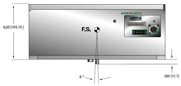
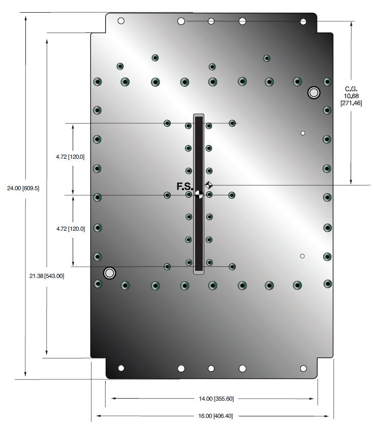
Dimensions:
24.00˝ x 16.00˝ x 6.50˝ (609.60mm x 406.40mm x 165.10mm)
Weight:
125lbs (49.5kg) ±10lbs (±4.5kg)
Orientation:
Can be mounted in any orientation.
X-Ray Leakage:
Not to be greater than 0.5mR/hr at 5cm outside the external surface
Special Features:
Stationary or rotating CT application up to 90rpm at a max. radius of 24.75˝ (629mm) Corporate
AC INPUT POWER 3 PIN PHOENIX CONTACT
| Pin | Signal | Parameters |
|---|---|---|
| 1 | Line | Line |
| 2 | GND | GND |
| 3 | Neutral | Neutral |
ANALOG INTERFACE — 10 PIN PHOENIX CONTACT
| Pin | Signal | Parameters |
|---|---|---|
| 1 | X-Ray | +24Vdc = enable X-Ray |
| 2 | X-Ray Return | X-Ray Return |
| 3 | N/C | No Connection |
| 4 | kV Monitor Output | 0 to 9Vdc = 0 to 100% Rated Voltage |
| 5 | SGND | Signal Ground |
| 6 | mA Monitor Output | 0 to 9Vdc = 0 to 100% Rated Current |
| 7 | Fault | Open Collector, Open = No Fault |
| 8 | Relay N/C | HV On, 50V @ 1A maximum |
| 9 | Relay Common | HV On, 50V @ 1A maximum |
| 10 | Relay N/O | HV On, 50V @ 1A maximum |
RS-232 DIGITAL INTERFACE — 9 PIN FEMALE D CONNECTOR
| Pin | Signal | Parameters |
|---|---|---|
| 1 | N/C | No Connection |
| 2 | Transmit Data | Conforms to E/A RS-232-C |
| 3 | Receive Data | Conforms to E/A RS-232-C |
| 4 | N/C | No Connection |
| 5 | SGND | Signal Ground |
| 6 | N/C | No Connection |
| 7 | N/C | No Connection |
| 8 | N/C | No Connection |
| 9 | N/C | No Connection |
Tablas y Diagramas
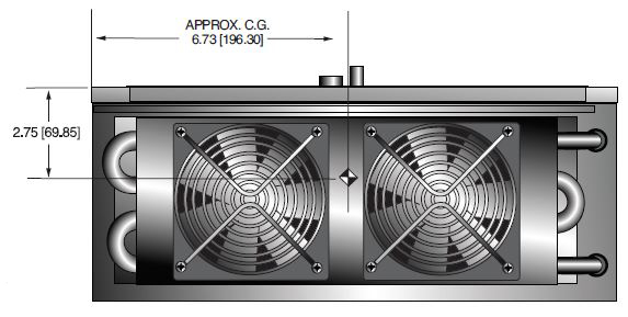
DIMENSIONS: in.[mm]
FRONT VIEW
BACK
TOP VIEW
SIDE VIEW
Frequently Asked Questions
Why Is Oil Insulation Used?
Do I Need to Ensure My Monoblock® Stays Cool? Why?
How Often Do I Need to Season My Monoblock® X-Ray Source? Why?
Application Notes AN-12 – The Benefit of Using a Current Source to Power X-Ray Tube Filament Circuits

