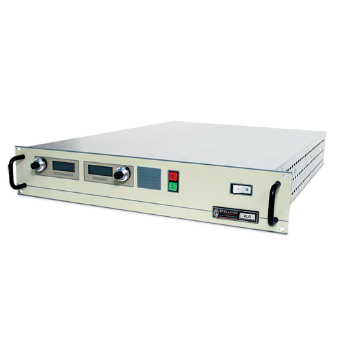
SERIE XLG
- Voltaje de salida de hasta 130 kV
- Alimentación de filamento con referencia a tierra
- "Ánodo caliente", polaridad positiva
- Programación local y remota
3-260W Industrial X-Ray Generators
La serie XLG de generadores de rayos X de Spellman son fuentes de alimentación de alto voltaje bien reguladas con salidas de voltaje de hasta 130 kV y de muy bajo rizo que se logra mediante el uso de técnicas avanzadas de conversión resonante. El voltaje extremadamente estable y las salidas de emisión de corriente tienen como resultado mejoras significativas de funcionamiento sobre la tecnología anteriormente disponible.
La serie XLG de generadores de rayos X proporciona toda la potencia, control y funciones de apoyo requeridas para las aplicaciones de rayos X, incluyendo la alimentación regulada para filamento de CD. Estas unidades incorporan programación local y remota, monitoreo, bloqueo interno de seguridad, protección contra cortocircuito y sobrecarga.
Aplicaciones típicas:
- Generador de rayos X para medición de enchapados
- Generador de rayos X para análisis de minerales
- Fuente de alimentación de alto voltaje para fluorescencia por rayos X

![]()
Especificaciones
(Ref. 128012-001 REV. M)
SPECIFICATIONS
Input Voltage:
115Vac±10%, 50-60Hz single phase or
220Vac±10%, 50-60Hz single phase.
Voltage and Current Control:
Local: continuously adjustable from zero to maximum rating via a ten-turn potentiometer with a lockable counting dial.
Remote: 0 to +10Vdc proportional from 0 to full output. Accuracy: ±1%. Input Impedance: 10Mohm.
Filament:
Specify at time of order:
FH: 9A, 3V.
FL: 3A, 3V.
Preheat level is 0.45 amps in standby
Voltage Regulation:
Load: 0.005% of full output voltage no load to full load.
Line: 0.005% for input voltage range change.
Current Regulation:
Load: 0.05% of full current ±100µA from 0 to full voltage.
Line: 0.05% of rated current over specified input range.
Ripple:
0.03% rms below 1kHz.0.75% rms above 1kHz.
Temperature Coefficient:
100ppm/°C.
Stability:
0.01%/8 hrs after 1/2 hour warm-up.
0.02% per 8 hours (typical).
Cooling:
Free air convection.
Metering:
Digital voltage and current meters (3.5 digits), 1% accuracy.
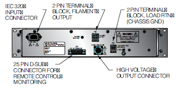
HV Output Cable:
10’ (3.3m) of shielded HV cable removable at rear.
I/O Connectors:
25 pin D-type for control interface with mating connector provided.
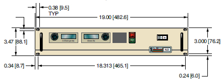
Dimensions:
30 to 60kV: 3.5”H x 19”W x 19”D (8.9cm x 48.3cm x 48.3cm).
80 to 130kV: 3.5”H x 19”W x 24”D (8.9cm x 48.3cm x 61.0cm).
Regulatory Approvals:
Compliant to EEC EMC Directive. Compliant to EEC Low Voltage Directive.
FRONT PANEL STATUS INDICATORS:
Overvoltage Voltage Control Mode
Overtemperature Current Control Mode
Regulation Error Interlock Open
Arc Interlock Closed
HV ON: Red HV OFF: Green
OPTIONS
APT - Adjustable Power Trip
AT - Arc Trip
SS(x) - Non-Standard Slow Start
NSS - No Slow Start
IO - Instant ON
LL(x) - Extra Length HV Cable
SL - Slides
Electronic Component (Power Source)
XLG series is intended for installation as a component of a system. It is designed to meet CE standards, with conditions of acceptance often being: customer provided enclosure mounting, EMC filtering, and appropriate protection, and isolation devices. The XLG series is not intended to be operated by end users as a stand-alone device. The XLG series power supply can only be fully assessed when installed within a system, and as a component part within that system.
XLG INPUT CURRENT
| Model | 115Vac | 220Vac |
|---|---|---|
| 3W-30W | 0.6A | 0.3125A |
| 40W-60W | 1.2A | 0.625A |
| 70W-150W | 3.0A |
1.56A |
| 160W-260W | 5.25A |
2.71A |
XLG SELECTION TABLE 0.1mA, 0.2mA , 0.5mA
| kV | 0.1mA | 0.2mA | .5mA |
|---|---|---|---|
| 30 | XLG30P3* | XLG30P6* | XLG30P15* |
| 35 | XLG35P3.5* | XLG35P7* | XLG35P17.5* |
| 40 | XLG40P4* | XLG40P8* | XLG40P20* |
| 50 | XLG50P5* | XLG50P10* | XLG50P25* |
| 60 | XLG60P6* | XLG60P12* | XLG60P30* |
| 80 | XLG80P8* | XLG80P16* | XLG80P40* |
| 100 | XLG100P10* | XLG100P20* | XLG100P50* |
| 120 | XLG120P12* | XLG120P24* | XLG120P60* |
| 130 | XLG130P13* | XLG130P26* | XLG130P65* |
*Specify FH for High power (27W) filament, FL for Low power (9W) filament.
XLG SELECTION TABLE 1.0mA, 2.0mA, 3.0mA
| kV | 1.0mA | 2.0mA | 3.0mA |
|---|---|---|---|
| 30 | XLG30P30* | XLG30P60* | XLG30P90* |
| 35 | XLG35P35* | XLG35P70* | XLG35P105* |
| 40 | XLG40P40* | XLG40P80* | XLG40P120* |
| 50 | XLG50P50* | XLG50P100* | XLG50P150* |
| 60 | XLG60P60* | XLG60P120* | XLG60P180* |
| 80 | XLG80P80* | XLG80P160* | --- |
| 100 | XLG100P100* | XLG100P200* | --- |
| 120 | XLG120P120* | XLG120P240* | --- |
| 130 | XLG130P130* | XLG130P260* | --- |
*Specify FH for High power (27W) filament, FL for Low power (9W) filament.
XLG CONNECTOR 25 PIN
| Pin | Signal | Signal Parameters |
|---|---|---|
| 1 | Power Supply Common | Signal Ground |
| 2 | External Inhibit | Ground=Inhibit, Open=HV On |
| 3 | External Interlock | +15V at Open, <15mA at Closed |
| 4 | External Interlock Return | Return for Interlock |
| 5 | Current Monitor | 0 to 10V=0 to 100% Rated Output |
| 6 | kV Test Point | 0 to 10V=0 to 100% Rated Output |
| 7 | +10V Reference | +10V, 1mA Max |
| 8 | Remote Current Program In | 0 to 10V=0 to 100% Rated Output |
| 9 | Local Current Program Out | Front Panel Program Voltage |
| 10 | Remote Voltage Program In | 0 to 10V=0 to 100% Rated Output |
| 11 | Local Voltage Program Ou | Front Panel Program Voltage |
| 12 | Power Monitor | 0 to 10V=0 to 100% Rated Output (Optional) |
| 13 | Remote Power Program I | 0 to 10V=0 to 100% Rated Output (Optional) |
| 14 | Local HV Off Out | +15V at Open, <25mA at Closed Connect to HV OFF for Fp Operation |
| 15 | HV Off | +15V at Open, <25mA at Closed Connect to HV OFF for Fp Operation |
| 16 | Remote HV On | +15V, 10mA Max=HV Off 0=HV On, +15V, 10mA Max=HV Off |
| 17 | Remote HV Off Indicator | +15V, 10mA Max=HV Off 0=HV On, +15V, 10mA Max=HV Off |
| 18 | Remote HV On Indicator | 0=HV Off, +15V, 10mA Max=HV O |
| 19 | Remote Voltage Mode | Open Collector 50V Max, 10mA Max On=Active |
| 20 | Remote Current Mode | Open Collector 50V Max, 10mA Max On=Active |
| 21 | Remote Power Mode | Open Collector 50V Max, 10mA Max On=Active |
| 22 | Remote PS Fault | 0=Fault, +15V, 0.1mA Max=No Fault |
| 23 | +15V Output | +15V, 100mA Max |
| 24 | Power Supply Common | Signal Ground |
| 25 | Shield Return | Shield Return |
Tablas y Diagramas
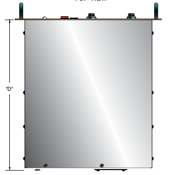
DIMENSIONS: in.[mm]
FRONT VIEW
TOP VIEW
BACK VIEW
Frequently Asked Questions
Application Notes AN-12 – The Benefit of Using a Current Source to Power X-Ray Tube Filament Circuits
Application Notes AN-13 – Arc Intervention Circuitry and External Series Limiting Resistors
Application Notes AN-14 – The Limits of Front Panel Digital Meters
Application Notes AN-15 – 3.5 And 4.5 Digit Meter Displays Explained
Application Notes AN-23 – SL HV Off and HV on Circuitry Explained
Application Notes AN-01 – Fundamentals of X-Ray Generator – X-Ray Tube Optimization

