Serie MXE
- Módulos inversores de polaridad conmutables en vivo de 2.5 kV a 10 kV, a 200μA.
- Control analógico diferencial, RS-232 y RS-485.
- Alta estabilidad, coeficiente de temperatura bajo.
- Rizo y Ruido ultra bajos, especificados hasta la banda 1/f.
- Interfase gráfica gratuita para pruebas y trabajo de desarrollo.
*Nota: Todas las especificaciones están sujetas a cambios sin previo aviso. Consulte la versión PDF en inglés de esta hoja de datos para obtener la revisión más actualizada.


Módulos De Inversión De Polaridad Conmutables en Caliente De Precisión
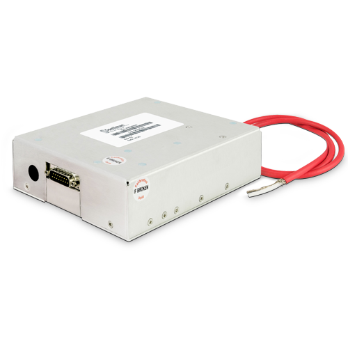
La serie MXE de Spellman es una familia de módulos de alto voltaje, de alto rendimiento, ultra compacta y de inversión de polaridad conmutable en vivo, con voltajes de salida que van desde 2.5 kV hasta 10 kV.
Las unidades de la serie MXE cuentan con múltiples opciones de control: analógico diferencial, RS-232 y RS-485 (semidúplex). La avanzada tecnología de Spellman, de bajo ruido y alta estabilidad, proporciona la alta calidad y rendimiento necesarios para aplicaciones de precisión.
Aplicaciones Tipicas:
- Espectrometría de masas
- Equipos de Prueba Automáticos
- Electroforesis capilar
- Análisis de superficies de iones duales
- Impresión electrostática
- Lentes electrostáticas
- Electrohilado
- Laboratorio de Precisión
Especificaciones
(Ref. 128162-001 REV. C)
SPECIFICATIONS
Input Voltage:
+24Vdc, ±1.2Vdc
Input Current:
0.5A maximum
Output Voltage:
3 models available: ±2.5kV, ±5kV and ±10kV
Minimum programmable voltage and max offset when programmed to 0V or disabled:
MXE2.5: ±50V
MXE5 and MXE10: ±75V
The output is not designed to sink current
Output Polarity:
Hot-switchable polarity reversing
Output Current:
200μA maximum
Voltage Regulation:
Line: For a 5% line change 20ppm
Load: 0-100% load 20ppm
Accuracies:
Voltage Control and Monitor: ±1% or ±10V*
Current Monitor ±5% or ±2μA*
Current Control (Digital): ±2% or ±2μA*
*whichever is greater
Voltage Program Repeatibility: ±0.1%
Current Limit:
230μA to 250μA
Polarity Reversal Time:
5s to within 2ppm
0.5s to within 99% at max output voltage and up to 100pF connected capacitance
Output Decay Time:
5s to <50V at no-load condition
Ripple:
≤30mV between 0.01Hz and 20MHz
Stability:
≤15ppm/8h after one hour warm up period
Temperature Coefficient:
≤15ppm per degree C
Protection:
Arc and short circuit protected. Not designed to withstand continuous arcing.
The power supply will fully recover once the short is removed.
Digital Features:
The following features are available when operating in digital control mode.
- Multiple units operation - Current control (min controllable current: 5μA)
- Programmable current and voltage ramps
Environmental:
Temperature Range:
Operating: 10˚C to 45˚C
Storage: -20˚C to 85˚C
Humidity:
5% to 90% RH, non-condensing
Cooling:
Convection cooled
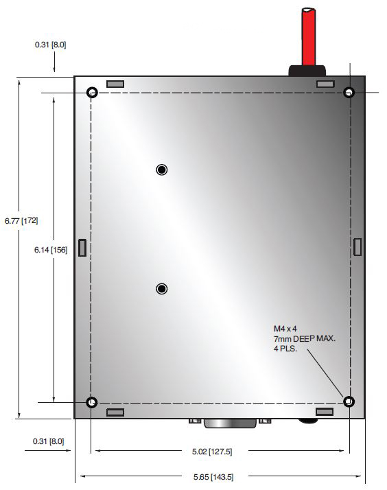
Dimensions:
1.9˝ H X 5.7˝ W X 6.8˝ D (48mm x 144mm x 172mm)
Weight:
3.74 lbs (1.7kg)
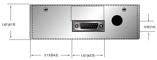
Interface Connector:
15 pin male D connector
Output Connectors:
Captive 39.4˝ (1 meter) long un-terminated shielded HRG58 HV cable (URM76 compatible)
Regulatory Approvals:
Compliant to EEC Low Voltage Directive UL/CUL recognized, File E354595.. UK Conformity Assessed. RoHS Compliant.
MXE SELECTION TABLE
| Model | OutputVoltage | Output Current |
|---|---|---|
| MXE2.5PN24 | ±2.5kV | 200μA |
| MXE5PN24 | ±5kV | 200μA |
| MXE10PN24 | ±10kV | 200μA |
MXE EXTERNAL INTERFACE—15 PIN MALE D CONNECTOR
| PIN | SIGNAL | SIGNAL PARAMETERS |
|---|---|---|
| 1 | 24Vdc Return | Input voltage return |
| 2 | +24Vdc Input | Input voltage +24dc @ 0.5A max |
| 3 | Voltage Monitor Output | 0 to 10Vdc = 0 to 100% rated output, Zout=330Ω |
| 4 | Polarity Set Input |
TTL level or open/short contact signal. Low or short = Positive, high or open = Negative |
| 5 | Comms Select | Comms Select / TTL level or open/short signal. Low or short = RS485, high or open = RS232 |
| 6 | Voltage Program Return | 0 to 10Vdc differential between pin 7 and pin 6 = 0 to 100% of rated output, Zin=100kΩ |
| 7 | Voltage Program Input | 0 to 10Vdc differential between pin 7 and pin 6 = 0 to 100% of rated output, Zin=100kΩ |
| 8 | Current Monitor Output | 0 to 10Vdc = 0 to 200μA, Zout=330Ω |
| 9 | RS232 RxD/RS485+ | Receive data (input) wrt pin 11 or RS485 non-inverting |
| 10 | RS232 TxD/RS485- | Transmit data (Output) wrt pin 11 or RS485 inverting |
| 11 | Signal Ground | Signal ground for control and monitoring |
| 12 | Enable Input | TTL level or open/short contact signal. Low or short = enabled, high or open = disabled |
| 13 | VProg A | Connect to pin 14 for analog Vprog control |
| 14 | VprogINT | Connect to pin 13 for analog Vprog or pin 15 for digital Vprog |
| 15 | Vprog D | Connect to pin 14 for digital VProg control |
Note: The MXE starts in analogue control at power on, if digital communication is detected, it switches to and remains in digital mode until power cycled.
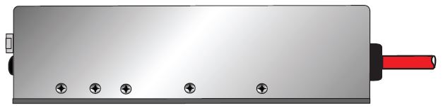
Tablas y Diagramas
DIMENSIONS: in.[mm]
FRONT VIEW

BOTTOM VIEW
REAR VIEW
SIDE VIEW