XRV I/O
- Mains to Cooler/Chiller, XRV Generator and XRV Touch Screen Controller
- Integrates all Necessary Safety Mechanisms to X-Ray System Environment to Meet International Standards
- X-Ray On, Pre-Warn and Safety Circuit Lamps
- Monitors Tube Cooling and Door Interlocks
- Rack and Wall Mount Versions Available
- Fail Safe Interlock Option Available
*Note: All specifications are subject to change without notice. Please consult the English PDF version of this datasheet for the most up-to-date revision.

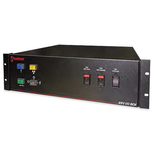
X-Ray Generator System Interface Box
Spellman’s optional XRV I/O box is the ideal accessory for integrating Spellman’s XRV X-Ray generators to a system environment. The XRV can now easily be packaged with industry standard metal ceramic X-Ray tubes, coolers and chillers while meeting all necessary safety and interlock requirements. The XRV I/O box is capable of accommodating a number of control interface options and can be installed in rack or wall configurations to best suit the integrators system placement requirements.
Typical applications:
- Power distribution for system components
사양
(Ref. 128112-001 REV.B)
Input Voltage:
180-264Vac, 50/60Hz
Operating Temperature:
0°C to +50°C
Storage Temperature:
-20°C to +80°C
Humidity:
0% to 95% relative humidity, non-condensing
Cooling:
Convection
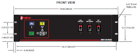
Dimensions:
19.0"W X 5.21"H X 18.00"D (482.6mm X 132.33mm X 330.2mm)
Weight:
30lbs (11.19kg)
Regulatory Approvals:
Compliant to EEC EMC Directive. Compliant to EEC Low Voltage Directive. RoHS Compliant
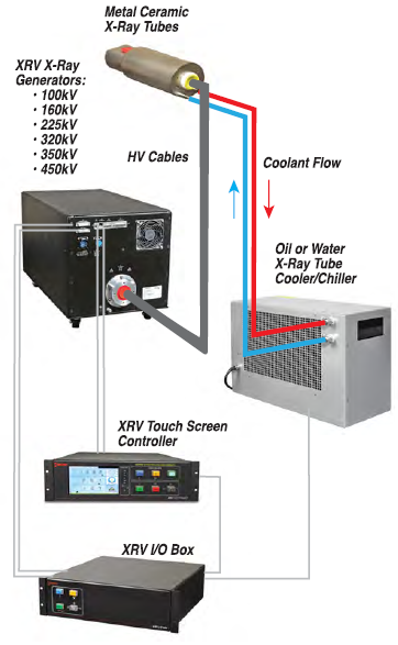
Typical system set-up:
XRV I/O BOX SELECTION TABLE
| MODELNUMBER | DESCRIPTION |
|---|---|
| XRV-9-1 | XRV I/O Box - Rack mount without XRV controller |
| XRV-9-2 | XRV I/O Box - Rack mount with XRV controller |
| XRV-9-3 | XRV I/O Box - Wall mount without XRV controller |
| XRV-9-4 | XRV I/O Box - Wall mount with XRV controller |
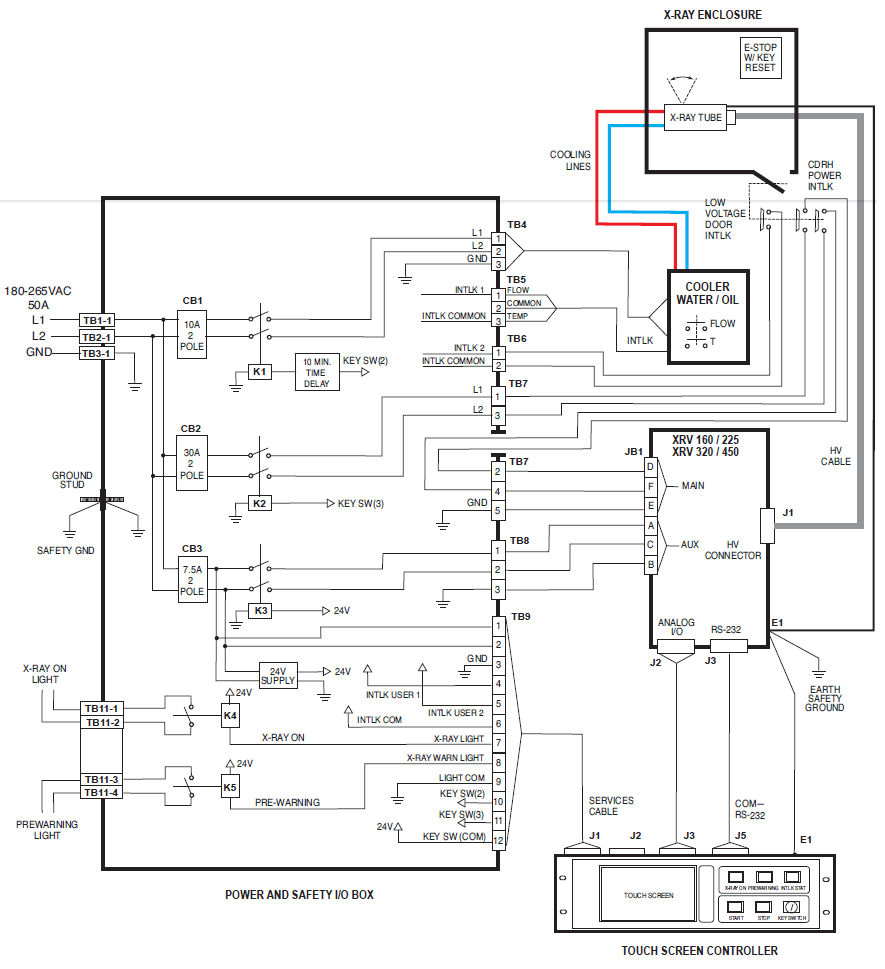
TB1, TB2, TB3-MAIN AC INPUT POWER—
| PIN | SIGNAL | PARAMETERS |
|---|---|---|
| TB1-1 | Line 1 | 180 - 264Vac |
| TB2-1 | Line 2 | Neutral or 180 - 264Vac (3 phase source) |
| TB3-1 | GND | Ground |
TB4- COOLER / CHILLER—MAINS AC OUTPUT
| PIN | SIGNAL | PARAMETERS |
|---|---|---|
| 1 | Line 1 | 180 - 264Vac |
| 2 | Line 2 | 180 - 264Vac or Neutral |
| 3 | GND | Ground |
TB5-COOLER / CHILLER INTERLOCKS
| PIN | SIGNAL | PARAMETERS |
|---|---|---|
| 1 | Flow INTLK | Dry contacts, ≤24Vdc |
| 2 | Common | Dry contacts, ≤24Vdc |
| 3 | Temp INTLK | Dry contacts, ≤24Vdc |
TB6-LOW VOLTAGE / DOOR INTERLOCKS
| PIN | SIGNAL | PARAMETERS |
|---|---|---|
| 1 | Door INTLK | Dry contacts, ≤24Vdc |
| 2 | Door INTLK | Dry contacts, ≤24Vdc |
TB7-XRV I/O MAINS TO CDRH* SAFETY INTERLOCK
| PIN | SIGNAL | PARAMETERS |
|---|---|---|
| 1 | Power INTLK Line 1 OUT | 180 - 264Vac |
| 2 | Line 1 IN | 180 - 264Vac |
| 3 | Power INTLK Line 2 OUT | Neutral or 180 - 264Vac (3 phase source) |
| 4 | Line 2 IN | Neutral or 180 - 264Vac (3 phase source) |
| 5 | GND | Ground |
TB8-XRV AUX AC OUTPUT—TO XRV JB1
| PIN | SIGNAL | PARAMETERS |
|---|---|---|
| A | Line 1 | 180 - 264Vac |
| B | Line 2 | Neutral or 180 - 264Vac (3 phase source) |
| C | GND | Ground |
TB9-XRV I/O TO XRV CONTROLLER INTERFACE
| PIN | SIGNAL | PARAMETERS |
|---|---|---|
| 1 | Line 1 | 180 - 264Vac |
| 2 | Line 2 | Neutral or 180 - 264Vac |
| 3 | GND | Ground |
| 4 | INTLK 1 | Dry contacts, ≤24Vdc |
| 5 | INTLK 2 | Dry contacts, ≤24Vd |
| 6 | INTLK Common | Common for INTLK 1, 2 |
| 7 | X-Ray ON Light | Dry contacts, ≤24Vdc |
| 8 | Pre-Warn Light | Dry contacts, ≤24Vdc |
| 9 | Light Common | Light common |
| 10 | Key Switch 2 | Dry contacts, ≤24Vdc |
| 11 | Key Switch 3 | Dry contacts, ≤24Vdc |
| 12 | Key Switch Common | Key common |
TB11-X-RAY ON / PRE-WARN LIGHTS
| PIN | SIGNAL | PARAMETERS |
|---|---|---|
| 1 | X-Ray ON Light | 180 - 264Vac, 5 amp |
| 2 | X-Ray ON Light | 180 - 264Vac, 5 amp |
| 3 | Pre-Warn Light | 180 - 264Vac, 5 amp |
| 4 | Pre-Warn Light | 180 - 264Vac, 5 amp |
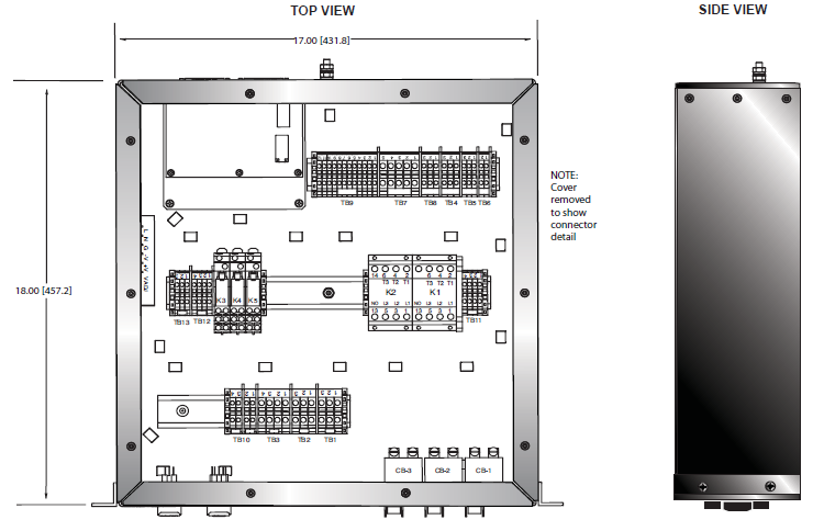
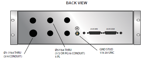
테이블 및 다이어그램
DIMENSIONS: in.[mm]
Frequently Asked Questions
What Are the Bandwidth Capabilities of the HVD Series of High Voltage Dividers?

