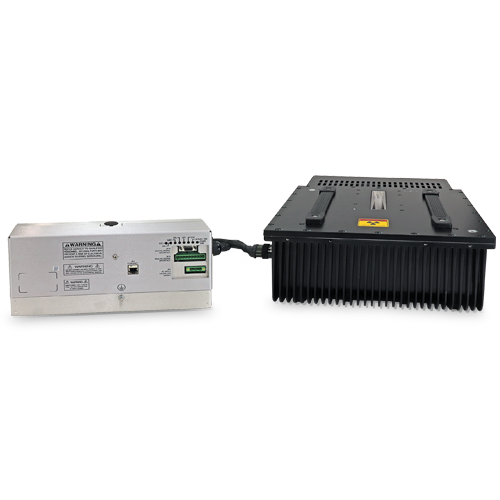
XRBHR Monoblock® Integrated X-Ray Source
- Compact & Lightweight
- Universal Input, Power Factor Corrected
- Can be Mounted in Any Physical Orientation
- Analog Monitoring Interface, Standard RS-232 Digital Interface and Ethernet
- Data Logging and Firmware Controlled X-Ray Tube Seasoning
*Note: All specifications are subject to change without notice. Please consult the English PDF version of this datasheet for the most up-to-date revision.

100W, 210W, 350W and 500W X-Ray Source
Spellman’s XRBHR (high reliability) Series of Monoblock® X-Ray sources are designed for OEM applications powering their internal Bipolar X-Ray tube at 80kV and 100kV at power levels of 100W, 210W, 350W and 500W. Features such as universal input, compact package size and a standard RS-232 digital interface simplify integration of any XRBHR model into your X-Ray system. Each XRBHR model is available with fan shaped (standard) or cone shaped (optional) beam geometries. Proprietary emission control circuitry provides excellent regulation of X-Ray tube current, along with outstanding stability performance. The XRBHR Series is designed for long field life and comes with a 3 year warranty.
TYPICAL APPLICATIONS
Food Inspection Systems, Fill Level Confirmation Systems, Security Scanning Systems, Industrial NDT Systems, Thickness/Plating Measurement Systems
사양
(Ref. 128132-001 REV. W)
Options:
CB Cone Beam
.5mm .5mm focal spot X-Ray tube
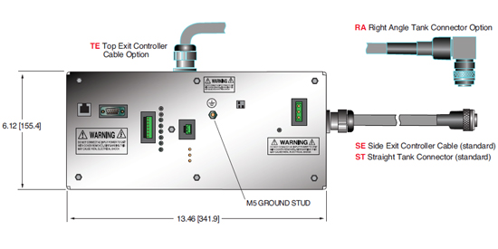
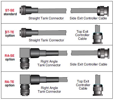
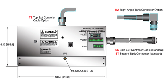
ST-TE See Cable Options
RA-SE See Cable Options
RA-TE See Cable Options
SPECIFICATIONS
X-Ray Characteristics:
Focal Spot: 0.8mm (IEC 336) standard
0.5mm (IEC 336) optional
Beam Filter:
Ultem: 1.50mm ±0.15mm
Oil: 9.0mm ±0.25mm
Glass: 1.7mm ±0.2mm
Be: 0.8mm
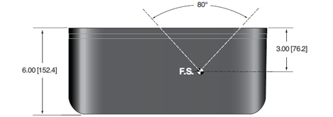
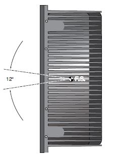
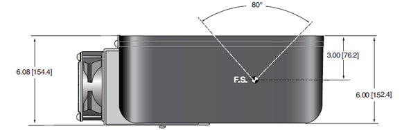
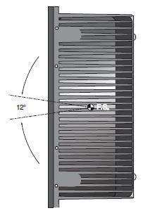
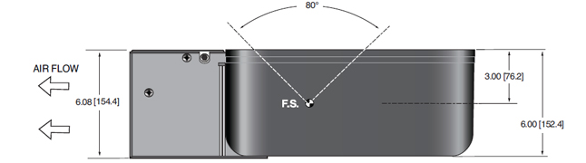
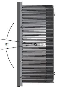
Beam Geometry:
Fan: Standard. The beam angular coverage will be 80° with the beam plane perpendicular to the X-Ray tube axis and 12° wide (with a 2° tolerance)
Cone: Optional. 40° cone beam (with a 2° tolerance)
Input Voltage:
100-240Vac, ±10%, 50/60 Hertz, .98 power factor
Input Current:
100W @ 2A
210W @ 4A
350W @ 6A
500W @ 8A
X-Ray Tube Voltage:
See table. Minimum kV for emission current 35kV
X-Ray Tube Current:
See table. Minimum emission current 150uA
X-Ray Tube Power:
See table
Voltage Regulation:
Line: ±0.05% of maximum output voltage over a ±10% change of nominal input line voltage
Load: ±0.1% of maximum rated voltage for 150uA to full rated load change
Voltage accuracy:
Voltage measured across the X-Ray tube is within ±2% of the programmed value
Voltage Risetime:
Standard ramp time shall be <500ms from 10% to 90% of maximum rated output voltage
Voltage Ripple:
0.5% peak to peak of maximum voltage for frequencies ≤1kHz
Emission Current Parameters
Current Regulation:
Line: ±0.05% of rated output current over a ±10% change of nominal input line voltage
Load: ±0.1% of rated output current for a change from 50% to 100% of rated output voltage
Current Accuracy:
Current measured through the X-Ray tube is within ±2% of the programmed value
Current Risetime:
Standard: Ramp time shall be <500ms from 10% to 90% of maximum rated current
Arc Intervention:
4 arcs in 10 seconds with a 100ms quench/100ms re-ramp = Shutdown
Filament Configuration:
Internal AC filament drive with closed loop filament emission control
Analog Interface:
Ground referenced 0 to 9Vdc for all monitoring signals.
Relay contacts and open collector signals for other signals. See analog interface connector pin out table.
Digital Interface:
The RS-232 interface allows for programming of kV, mA output and X-Ray enable. Provides monitoring for kV, mA output and oil temperature.
Operating Temperature:
0°C to +40°C
Storage Temperature:
-40°C to +70°C
Humidity:
10% to 95% relative humidity, non-condensing
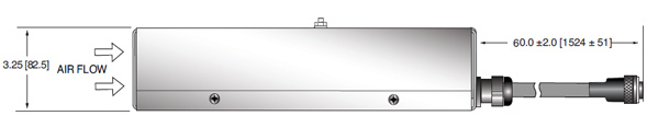
Cooling:
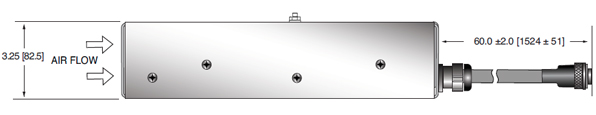
X-Ray Tank:
100W: Convection/customer supplied forced air so tank is < 55˚C
210W: Externally powered forced air cooling, 24Vdc @ 2A
350W: Externally powered forced air cooling with oil pump and heat exchanger, 24Vdc @ 5A
500W: Externally powered forced air cooling with oil pump and heat exchanger, 24Vdc @ 5A
Controller: Forced air via internal fan.
Grounding Point:
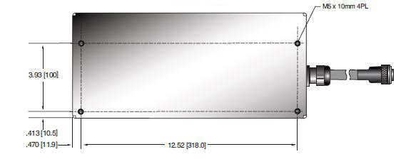
M5 ground female thread on tank
M5 ground stud on control chassis provided
Dimensions:
X-Ray Tank: See drawings
100W/210W Controller: See drawings
350W/500W Controller: See drawings
Weight:
X-Ray Tank:
100W @ 75 lbs. (34kg)
210W @ 75lbs. (34kg)
350W @ 81.5lbs. (37kg)
500W @ 81.5lbs. (37kgs)
Controller:
100W/210W: 4 pounds (1.18kg)
350W/500W: 7 pounds (3.18kg)
Orientation:
Can be mounted in any orientation.
X-Ray Leakage:
Not to be greater than 0.5mR/hr at 5cm outside the external surface.
Regulatory Approvals:
Compliant to EEC EMC Directive. Compliant to EEC Low Voltage Directive. UL/CUL recognized file E235530
MODEL SELECTION TABLE
| Model | Maximum Voltage | Maximum Current | Maximum Power |
|---|---|---|---|
| XRB80PN210HR | 80kV | 5.25mA | 210 watts |
| XRB80PN350HR | 80kV | 8mA | 350 watts |
| XRB80PN500HR | 80kV | 8mA | 500 watts |
| XRB100PN100HR | 100kV | 2mA | 100 watts |
| XRB100PN210HR | 100kV | 4.2mA | 210 watts |
| XRB100PN350HR | 100kV | 7mA | 350 watts |
| XRB100PN500HR | 100kV | 8mA | 500 watts |
LED INDICATORS
| INDICATOR | SIGNAL | CONDITION Illuminated When... | LED COLOR |
|---|---|---|---|
| 1 | OV Error 6 | High kV occurs | Red |
| 2 | UV Error 5 | Low kV occurs | Red |
| 3 | UC Error 4 | Low mA occurs | Red |
| 4 | OC Error 3 | High mA occurs | Red |
| 5 | ARC Error 2 | Arc fault occurs | Red |
| 6 | OT Error 1 | Over temperature occurs | Red |
| 7 | X-Ray On | X-Rays are being generated | Green |
| 8 | Power On | AC input power is present | Green |
| SMART XRB |
||
|---|---|---|
|
The XRBHR has two new digital features: data logging and firmware controlled seasoning. Data Logging: FAULT EVENTS The XRBHR stores data 620ms before the event, the event itself and for 620ms after the event. Data is recorded every 20ms (62 samples total) showing: We also log non-fault events, these are changes in set points or state of the unit. NON FAULT EVENTS Fault event data is actual graphical data. Non fault event data is just stored as event type, data and timestamp. We also have a preventative maintenance fault, which throws a non-shutdown fault if the X-Ray tube has been factory Firmware Controlled Seasoning: |
Power and Interface Connections
AC INPUT—3 PINPHOENIX CONTACT 1858772
| PIN | SIGNAL | PARAMETERS |
|---|---|---|
| 1 | AC Input (high) | 100-240Vac (high) |
| 2 | Ground | Ground |
| 3 | AC Input (neutral) | 100-240Vac (neutral) |
DC INPUT FOR HEAT DISSIPATION UNIT—4 PIN AMP (210/350/500W) 206060-1
| PIN | SIGNAL | DESCRIPTION | PARAMETERS |
|---|---|---|---|
| 1 | 24Vdc | Fan/Pump Power | 24Vdc @ 5 amps |
| 2 | 24Vdc Return | Fan/Pump Power | 24Vdc @ 5 amps |
| 3 | N/C | No Connection | N/C |
| 4 | N/C | No Connection | N/C |
ANALOG INTERFACE— 10 PIN PHOENIX CONTACT 1792605
| PIN | SIGNAL | PARAMETERS |
|---|---|---|
|
1 |
X-Ray Interlock Enable | Apply +24Vdc to enable interlock. Open/removal of +24Vdc will cause X-Ray generation to stop. |
| 2 | X-Ray Interlock Enable Return | Ground reference for X-Ray Interlock. |
| 3 | Pin removed | N/C |
| 4 | kV Monitor | 0-10Vdc = 0-100% rated output voltage. Zout = 10kΩ |
| 5 | Signal Ground | Signal Ground |
| 6 | mA Monitor | 0-10Vdc = 0-100% rated output current. Zout =10kΩ |
| 7 | Fault Signal | Open collector, High (Open) = No Fault, 35Vdc @ 10mA maximum |
| 8 | HV ON Lamp Relay N/O | N/O dry contacts. 50 volts maximum. Rated for 1 amp or less, 50mA nominal load |
| 9 | HV ON Lamp Relay C | Common dry contacts. 50 volts maximum. Rated for 1 amp or less, 50mA nominal load |
| 10 | HV ON Lamp Relay N/C | N/C dry contacts. 50 volts maximum. Rated for 1 amp or less, 50mA nominal load |
“It is critical to ensure that 24Vdc is supplied to pins 1 and 2”
RS-232 DIGITAL INTERFACE— 9 PIN MALE D CONNECTOR
| PIN | SIGNAL | PARAMETERS |
|---|---|---|
| 1 | N/C | N/C |
| 2 | Transmitted Data | Conforms to EIA RS-232-C |
| 3 | Received Data | Conforms to EIA RS-232-C |
| 4 | N/C | N/C |
| 5 | Signal Ground | Signal Ground |
| 6 | N/C | N/C |
| 7 | N/C | N/C |
| 8 | N/C | N/C |
| 9 | N/C | N/C |
ETHERNET DIGITAL INTERFACE— RJ45 8 PIN FEMALE CONNECTOR
| PIN | SIGNAL | PARAMETERS |
|---|---|---|
| 1 | TX + | Transmit Data + |
| 2 | TX - | Transmit Data - |
| 3 | RX + | Receive Data + |
| 4 | N/C | No Connection |
| 5 | N/C | No Connection |
| 6 | N/C | Receive Data - |
| 7 | N/C | No Connection |
| 8 | N/C | No Connection |
테이블 및 다이어그램
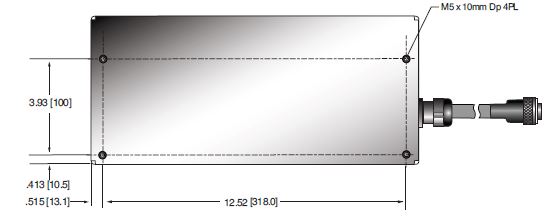
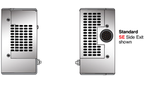
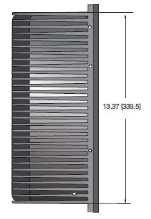
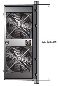
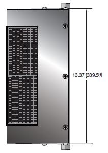
DIMENSIONS: in.[mm]
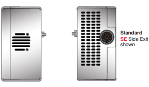
100/210W
CONTROL UNIT
FRONTVIEW
BOTTOM VIEW
REAR VIEW
SIDE VIEW
Cable Configurations
DIMENSIONS: in.[mm]
300/500W CONTROL UNIT
FRONT VIEW
BOTTOM VIEW
SIDE VIEW
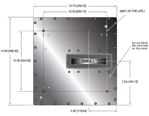
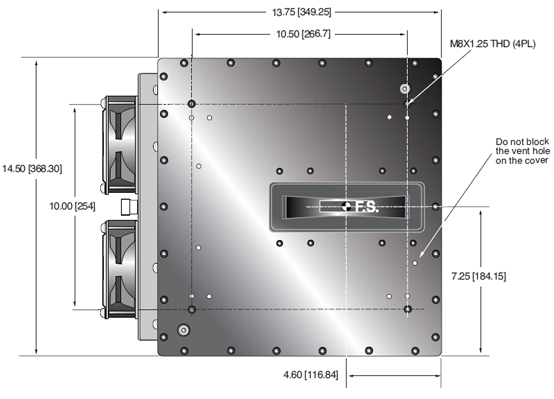
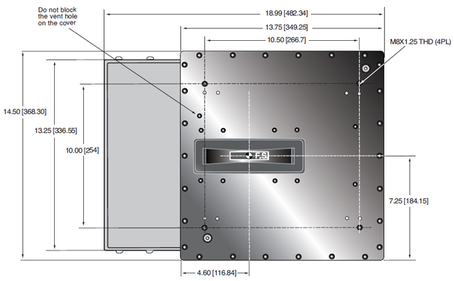
DIMENSIONS: in.[mm]
100W TANK
TOP VIEW
SIDE VIEW
BACK VIEW
FRONT VIEW
DIMENSIONS: in.[mm]
210W TANK
TOP VIEW
SIDE VIEW
BACK VIEW
FRONT VIEW
DIMENSIONS: in.[mm]
350/500W TANK
TOP VIEW
SIDE VIEW
BACK VIEW
FRONT VIEW
Frequently Asked Questions
Why Is Oil Insulation Used?
Do I Need to Ensure My Monoblock® Stays Cool? Why?
How Often Do I Need to Season My Monoblock® X-Ray Source? Why?
Application Notes AN-12 – The Benefit of Using a Current Source to Power X-Ray Tube Filament Circuits

