EBM-TEGR
- Triode Supply for Thermionic Emission SEM
- High Precision, Low Noise, Ultra Stable
- Over Current/Voltage, Arc and Short Circuit Protection
- RS-232 or RS-485 Digital Interface
- Free GUI for Testing and Development Work
- OEM Customization Available
- CE, UKCA and RoHS Compliant
*Note: All specifications are subject to change without notice. Please consult the English PDF version of this datasheet for the most up-to-date revision.


Integrated Triode Supply for Thermionic Emission SEM
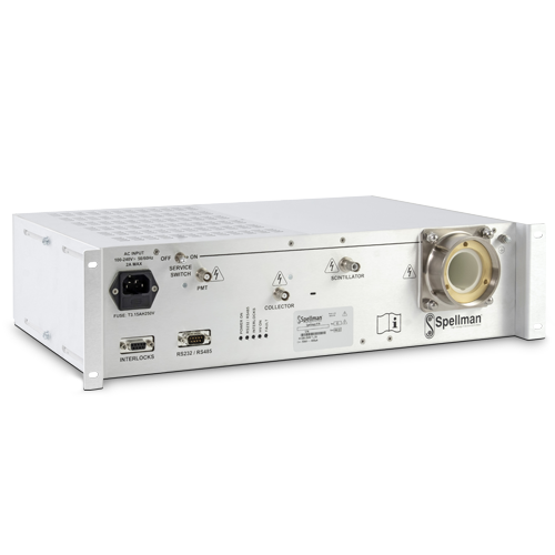
The EBM-TEGR is an integral solution that provides the high voltage required by Thermionic Emission Scanning Electron Microscope (SEM) in a 19'' rack mountable chassis.
Spellman’s proprietary packaging and encapsulation technology gives dramatic improvements in size, cost and performance compared to other SEM power supply offerings.
This unit provides a highly regulated, low noise, ultra stable Accelerator supply programmable up to -30kV at 400uA. This, together with Floating Filament and Grid supplies referenced to the Accelerator control the beam. The unit also includes high voltage outputs to drive the Detector, comprising PMT, Scintillator and Collector grounded outputs.
Customer control of this integrated EBM-TEGR power supply system is accomplished via RS-232 or the optional RS-485 interface. Five interlocks are provided. The unit is CE and UKCA marked.
사양
(Ref. 128031-001 REV. C)
SPECIFICATIONS
Input Voltage:
100 to 264 Vac @2A max. 47 to 63Hz
Temperature:
Operating: 10°C to +45°C
Storage: -10°C to +70°C
Humidity:
0 to 90% RH, non-condensing
Interlocks:
Five functional interlocks are provided on a 9 pin D connector (see pinout details).
The EHT, Collector, Scintillator and PMT interlocks disable the corresponding outputs when open (the other outputs can be powered up).
The Vacuum interlock disables the gun supplies (EHT and heater) when open.
Front Panel Indicators:
POWER ON: Green LED
INTERLOCKS: Yellow LED indicates that all the interlocks are closed and the unit is able to generate high voltage.
HV ON: Yellow LED indicates that the high voltage EHT (Accelerator) Output is energized.
RS-232/RS-485: Yellow LED indicates when communications are taking place on the RS-232/RS-485 bus.
FAULT: Red LED indicates that an Error condition has occurred.
Input Power Connector:
I.E.C. 320 Receptacle with integral fuse
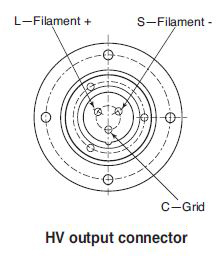
High Voltage Output Connectors:
Grid and Filament: Claymount CA1 type 03 (see drawing)
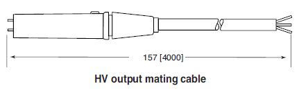
A mating cable assembly is available (see drawing and How To Order table)
Collector and PMT: BNC HT-MHV Receptacle Radiall R316553000
Scintillator: SHV Receptacle Radiall R317580000
Protection:
All outputs are protected from arcs in the load and continuous short circuit to ground and between each other.
- If the Beam Energy has more than 4 arcs in a 10 minutes period, unit will disable all outputs and sets all programs to zero.
- In case of an over temperature condition for greater than 100° C for ten seconds all outputs will be disabled.
- Over voltage, over current and internal communication issues are also monitored and trigger fault conditions.
- The unit reports fault or trip conditions through status flags. After a Trip occurs, the unit can be reset through software (digital interface) or power cycle.
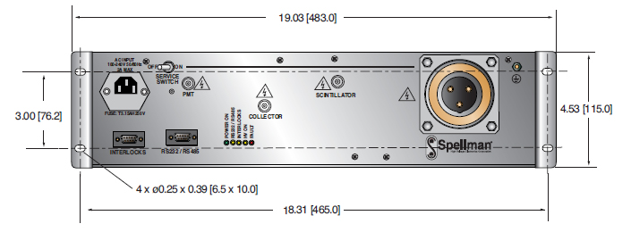
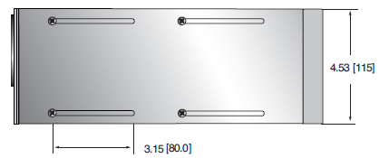
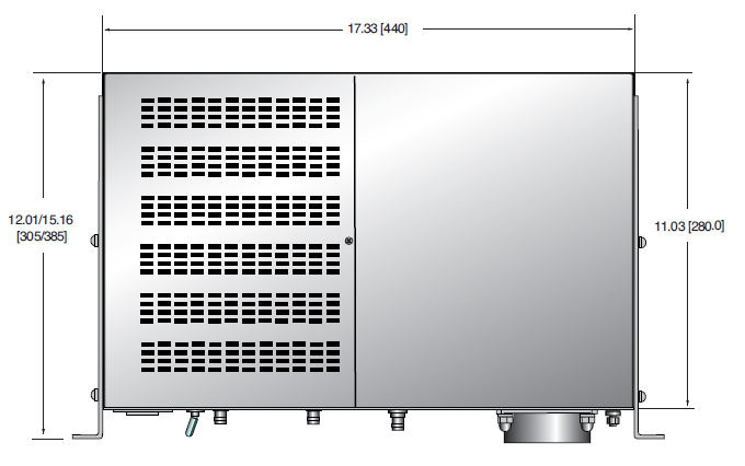
Dimensions:
See drawing
Weight:
39.7 lbs. (18kg)
Regulatory Approvals:
Compliant to EEC Low Voltage Directive. UK Conformity Assessed. RoHS Compliant.
OUTPUT SPECIFICATIONS
| OUTPUT | Accelerator (EHT) | Filament | Grid | PMT | Scintillator | Collector |
|---|---|---|---|---|---|---|
| Output Voltage | -100V to -30kV, referenced ground | 5V max, 15W max center tapped to the Accelerator | -35V to -1650V referenced to Accelerator | 0V to -1300V referenced to ground | +50V to +11kV referenced to ground | -400V to +400V referenced to ground |
| Output current - max | 400μA | 5A | 400μA | 1mA (current trip level: 1.2mA) | 200μA | 4μA |
| Accuracy | ±2% or ±30V (whichever is greater) | ±5% or ±100mA (whichever is greater) | N/A | ±2% or ±1V (whichever is greater) | <1% or ±10V (whichever is greater) | ±2% or ±2V (whichever is greater) |
| Load Regulation | <10ppm for 30μA to 400μA | <5mA for a 0.4Ω to 1Ω change at 3A | N/A | <±100ppm for 0 to 1mA | <100ppm for 10μA to 200μA | <5% for 0 to 5 mA |
| Line Regulation at full load ± 10% line change | <10ppm | <5mA | N/A | <100ppm | <100ppm | <10mV |
| Ripple p-p at max. output | <100mV | 1mA at 50Hz 30mV at 100kHz at 3A,1Ω | N/A | <200mV | <100mV | <25mV |
| Temperature Coefficient | <50 ppm/°C | <300 ppm/°C | N/A | <100 ppm/°C | <250 ppm/°C | <50 ppm/°C |
| Stability (1h warm up) | <10 ppm/15min <25 ppm/1h |
<2mA/1h | <0.4μA/15min | 200 ppm/1h | <1%/1h | <50mV/15min |
INTERLOCKS CONNECTOR 9 PIN D SUB-FEMALE
| Pin | Signal | I/O | Signal Parameters |
|---|---|---|---|
| 1 | 0V | - | Ground |
| 2 | 24V | O | 24V Output from unit (connected to pin 6 internally) |
| 3 | Collector | I | Input for collector interlock |
| 4 | Scintillator | I | Input for Scintillator interlock |
| 5 | Vacuum | I | Input for vacuum interlock (connected to pin 8 internally) |
| 6 | 24V | O | 24V output from unit (connected to pin 2 internally |
| 7 | EHT | I | Input for EHT interlock |
| 8 | Vacuum | I | Input for vacuum interlock (connected to pin 5 internally) |
| 9 | PMT | I | Input for PMT interlock |
DIGITAL COMMUNICATIONS CONNECTOR 9 PIN D SUB-MALE
| Pin | RS-232 | RS-485 | Description |
|---|---|---|---|
| 1 | - | - | N/C |
| 2 | RS-232 RxD | - | RS-232 data receive |
| 3 | RS-232 TxD | Z | RS-232 data transmit or RS-485 inverting |
| 4 | - | - | N/C |
| 5 | GND | GND | Ground |
| 6 | - | - | N/C |
| 7 | - | Y | RS-485 non-inverting |
| 8 | - | - | N/C |
| 9 | - | - | N/C |
HOW TO ORDER
| Description | Part Number |
|---|---|
| EBM-TEGR | EBM30N12/TEGR |
| EBM-TEGR with RS-485 option | EBM30N12/TEGR/DCC4 |
| HV Output cable - 4 meters | HVC75/3SO/1382 |
테이블 및 다이어그램
DIMENSIONS: in.[mm]
Side View
Top View
Front View