EBM-FEG
- Integrated Tetrode Supply for Field Emission SEM
- Very Low Ripple and Ultra Stable Outputs
- Robust Arc and Short Circuit Protection
- Designed to Minimize Micro-discharge Events
- Optically Isolated Digital Interface
- Free GUI for Testing and Development Work
- UL Recognized, CE Marked & Designed to Meet SEMI S2
*Note: All specifications are subject to change without notice. Please consult the English PDF version of this datasheet for the most up-to-date revision.


OEM Module For SEM Applications
Spellman’s EBM-FEG Series is an integrated, multiple output high voltage power supply specifically designed to drive Scanning Electron Microscope (SEM) Columns. Spellman’s extensive applications knowledge has enabled us to develop a range of technology platforms that can be customized to meet the demanding requirements of SEM.
The main Acceleration Voltage is a high stability 30kV supply, with integrated floating Filament, Extractor and Suppressor outputs required to drive Field Emission, Cold Cathode and Schottky Electron Sources in a compact solution with extenders to mount in a 19˝ rack. All outputs are offered with ultra-low output ripple, minimal microdischarge, excellent regulation, stability, temperature coefficient and accuracy specifications for unprecedented image quality and resolution. Isolation and control of the respective floating sources is provided via Spellman’s proprietary high voltage isolation techniques
Customer control of this integrated EBM-FEG power supply system is accomplished via a fiber optic RS-232 interface. All high voltage safety interlocks are of a fail safe hardware based design. The unit is UL and CE marked and is designed to be compliant with SEMI standards.
Typical Applications:Scanning Electron Microscopes (SEM)
Electron Beam Controller
사양
(Ref. 128136-001 REV. C)
Specifications
Input Voltage:
+24Vdc, ±5% @ 4 amps maximum. Inrush is <6 amps for 1 second.
Environmental:
Operating Temperature: +10°C to +45°C ambient for normal operation. The unit will operate from 0°C but will require an extended warm up period.
Storage Temperature:
-20°C to +60°C
Humidity:
0 to 80% RH, non-condensing
Altitude:
2000 meters ASL at full power. For altitudes above 2000 meters the maximum ambient operating temperature is linearly derated by 1.1˚C per 300 meter interval.
Mechanical:
The unit is provided with a pair of removable mounting flanges; these allow the unit to mount in a 19” rack system. The unit can be operated in any orientation.
Vacuum Interlock:
The vacuum interlock is an optical interlock which is made when light is present on the fiber. When no light is present the interlock is broken and the unit disables all of the outputs.
Front Panel Indicators:
Power On:
An illuminated green LED indicates that +24V power is present and it will be illuminated over the range 22.8 to 25.2 volts and will flash with a 1 second period when out of range.
Vacuum Interlock:
An illuminated yellow LED indicates that the vacuum interlock is closed. The vacuum interlock LED must be illuminated for the unit to be able to generate high voltage.
Test GUI:
A product GUI can be provided free of charge for customer testing and development work.
Protection:
All outputs are protected from arcs in the load and continuous short circuit to ground and between each other.
All low voltage inputs are protected against over voltages of ±30 volts. The power input is protected against over voltage and reversed connection.
If the Beam Energy has more than ‘A’ arcs in a nominal ‘B’ time (sec) period the unit will disable all outputs and sets all programs to zero.
If there are less than ‘A’ arcs the unit will continue to operate. The default values are A = 8 and B = 10. Both ‘A’ and ‘B’ are settable via optical bus commands and GUI.
In case of an over temperature condition for greater than ten seconds all outputs will be disabled.
The unit reports fault or trip conditions through status flags. After a Trip occurs (arc, over current, over voltage, temperature etc.), the unit can be reset through software (optical bus command) or power cycle.
Weight:
44 lbs. (20kg)
Regulatory Approvals:
UL recognized component (RC). File number E354595. Compliant to IEC/UL 61010-1 Safety requirements for electrical equipment for measurement, control and laboratory use; CAN/CSA-C22.2 No.61010-1. CE marked to EN 61010-1. UKCA marked to BS EN 61010-1. RoHS compliant.
As the unit is designed for incorporation within the user’s system it is not tested against any specific EMC standards. The user will need to take appropriate EMC precautions when designing the unit in and verify the overall system EMC performance against any relevant standards.
OUTPUT SPECIFICATIONS
| OUTPUT | Beam Energy | Filament | Suppressor | Extractor |
|---|---|---|---|---|
| Output Voltage | -20V to -30kV referenced to ground. Amplitude does not exceed 35kV and is <60 V when output disabled. Conditioning voltage -32.5kV at zero load current. | nominal 1.8V max 3V referenced to Beam Energy | -100V to -1kV referenced to Beam Energy | 100V to 10kV referenced to Beam Energy |
| Output current - max | 200μA | 3A | 100μA | 700μA |
| Current Trip | 250μA ±10% for 1s Output disabled and program set to zero |
>3.15A for 10s All outputs disabled and programs set to zero | >100mA ±10% for 5s. All outputs disabled and programs set to zero | Programmable 0 to 735μA. All outputs disabled and programs set to zero |
| Accuracy | <1% or ±10V (whichever is greater) | ±5mA (between 2A to 3A) | <2% or ±6V (whichever is greater) | <1% or ±20V (whichever is greater) |
| Linearity | <± 25V | ±10mA (between 0.5A to 3A) | ±5V | ±20V |
| Load Regulation | <±100mV for 30μA to 200μA | <5mA for 0.4Ω to 1Ω change at 3A | <120mV for 10μA to 100μA | <100mV at 40μA 0.1Hz to 20MHz, <1V at 10 - 700μA |
| Line Regulation for a ± 5% line change | <10ppm | <1mA | <5ppm | <5ppm |
| Ripple p-p at max. output | <50mVp-p 0.1Hz to 20MHz | <1mAp-p 20Hz to 10kHz <30mVp-p at approx 100kHz |
<20mVp-p at 0.1Hz to 20MHz | <100mV p-p at 0.1Hz to 20MHz |
| Temperature Coefficient | <5 ppm/°C from 20°C to 30°C, <10 ppm/°C otherwise | <50 ppm/°C | <50 ppm/°C | <25 ppm/°C |
| Stability (1h warm up) | 200mV/15min | <0.5mA/60min | <0.3V/15min | <0.3V/15min |
| Ramp Rate Programable Range |
50 to 5000 V/s | 1 to 3000 mA/s | 10 to 1000 V/s | 10 to 1000 V/s |
| Voltage Monitor Resolution | 0.5V | 2.5mV | 0.25V | 2.5V |
| Voltage Monitor Accuracy | ±2% or ±10V | ±5% or ±25mV | ±2% or ±250mV | ±1% or ±20V |
| Current Monitor Resolution | 100nA | 1mA | 0.25μA | 0.25μA |
| Current Monitor Accuracy | ±2% or ±1μA | ±10mA | ±10% | ±2% or ±2μA |
| Additional info | Programmable Wobble feature. Sinusoidal, amplitude up to 5% Beam Energy voltage, 0.5Hz to 1.6Hz |
Open Circuit detection: Vout > 5.2 ± 0.1V All outputs disabled and programs set to zero. Filament supply optimized for a nominal load resistance of 0.6Ω |
INPUT POWER CONNECTOR
UNIVERSAL MATE-N-LOK 1-350942-0
| Pin | Signal | Signal Parameters |
|---|---|---|
| 1 | +24Vdc | +24Vdc @ 4A |
| 2 | Power Ground | Power Ground |
VACUUM INTERLOCK CONNECTOR
The vacuum interlock connector is a dual channel Avago
HFBR- 2524z/1524z connector.
OPTICAL COMMUNICATIONS CONNECTOR
The fiber optics communications connector is a dual channel Avago HFBR- 2524z/1524z connector. A suitable Serial to optical communication kit including fiber optic cables, optic to RS-232 converter, RS-232 extension lead and RS-232 to USB cable is available. Optical to RS-232 converter can be ordered separately.
See HOW TO ORDER table
HIGH VOLTAGE OUTPUT CONNECTOR
The unit uses a custom high voltage 4 pole receptacle. A mating cable assembly in different lengths is available.
See HOW TO ORDER table.
HOW TO ORDER
| Description | Part Number |
|---|---|
| EBM-FEG | EBM30N6/FEG |
| Optical to RS-232 Communication Kit | EBMKFEG |
| Optical to RS-232 Converter (included in the above kit) | 21777 |
| HV Output Cable - 1.5 meters | HVC30/4ISO/1201 |
| HV Output Cable - 2.8 meters | HVC30/4ISO/1197 |
테이블 및 다이어그램
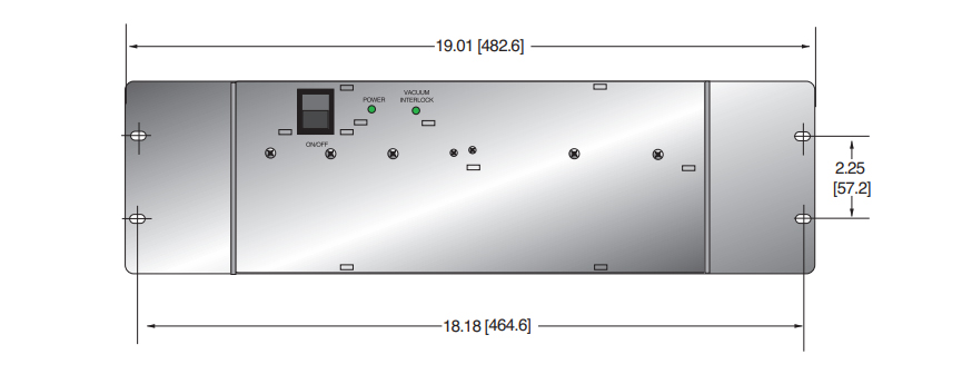
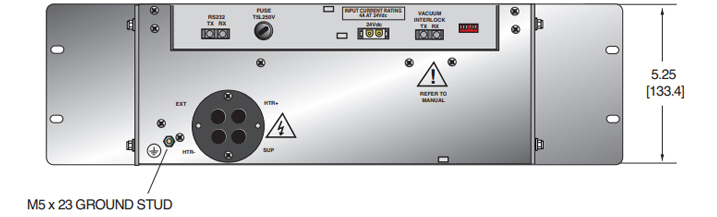
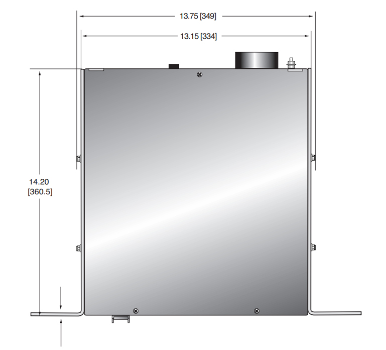
DIMENSIONS: in.[mm]
REAR VIEW
TOP VIEW
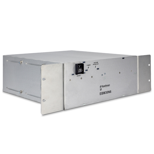
FRONT VIEW